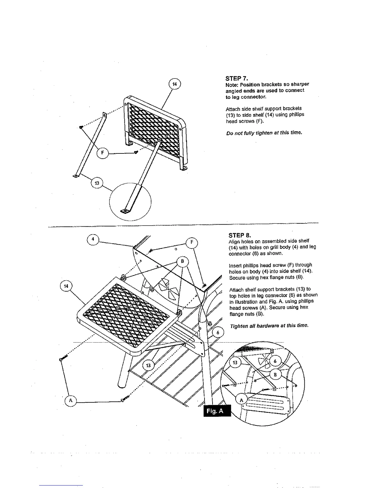
STEP 7.
Note: Position brackets so sharper
angled ends are used to connect
to leg connector.
Attach side shelf support brackets
(13) to side she(f (t4) using phii_ips
head screws (F).
Do not fu!ly tighten at this time.
STEP 8.
Align holes on assembled side shelf
(14) with holes on gri)l body (4) and leg
connector (6) as shown.
Insert phillips head screw (F) through
holes on body (4) into side shelf (t4),
Secure using hex flange nuts (B).
Attach sheJf suppozt brackets (13) to
top hofes in leg connector (6) as shown
in illustration and Fig, A, using phillips
head screws (A). Secure using hex
flange nuts (B).
Tighten all hardware at this time,