ROUTER TABLE - 054-6938-6
20
Adjusting the cutting height
NOTE: This method of adjusting the cutting height is applicable only to the fixed-base router that is
included with this router table (Model No. 054-6908-8) or CTC Model No. 054-6810-8.
NOTE: A 5" (12.7 cm) long, 3/16" (5 mm) diameter hex wrench is required for this operation (not included).
The cutting height can be adjusted by turning the Fine Adjustment Dial clockwise or counter-clockwise
with a hex wrench.
NOTE: Be sure that the worm-gear system in the router is engaged before making adjustments. First
turn off the table switch by pushing down on the ON/OFF switch, then test that the gear is engaged by
turning the Adjustment Dial on the router clockwise and counter-clockwise to see if the bit lowers and
rises. If it does not, press Rough Adjustment Knob on the router, and turn the Fine Adjustment Dial until
the gears engage.
1. Turn off the table switch by pushing down on the ON/OFF switch.
2. Loosen the clamping lever on the router.
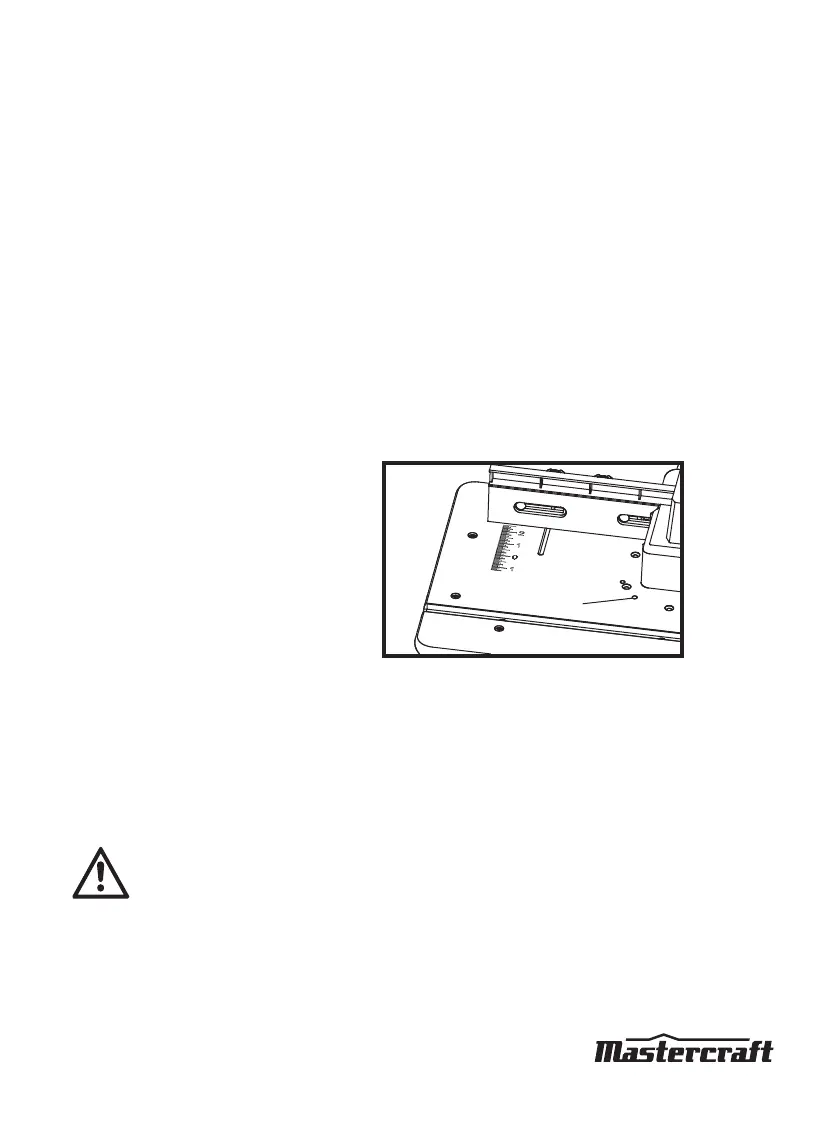
3. Insert the hex wrench into the adjusting hole
on the tabletop (fig 16), and use the hex
wrench to turn the router adjustment dial
clockwise in order to move the router collet
down, or counter-clockwise in order to move
the collet up.
4. Once the desired cutting height is set, tighten
the clamping lever on the router.
Using the router with the router table
1. Read and understand entire Instruction Manual for the router.
2. Attach the router to the router table as directed on page 14.
3. Make sure the router-table switch is off. Lock the router switch in the ON position.
4. Plug the power cord for the router table into a power source.
WARNING!
Always plug the router into the switched outlet in the router table. Never plug a router-table
mounted router into another power source.
5. Turn on the power to the router table by pulling up on the ON/OFF switch.
6. Always control the power to the router using the switch on the router table whenever the router is
mounted on the table.
OPERATING INSTRUCTIONS
Adjusting Hole
fig 16
 Loading...