22 23
model no. 055-6761-2 | contact us 1-800-689-9928
ASSEMBLY AND ADJUSTMENTS
• Repeat steps until the blade is at 45° to the mitre table.
• Tighten bevel lock knob and locknut when alignment is achieved.
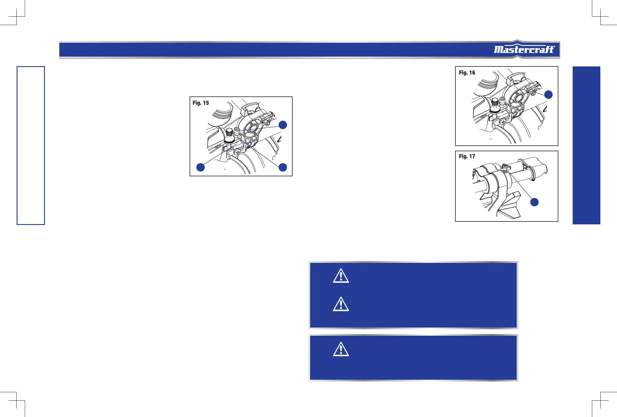
MAXIMUM CUTTING DEPTH (Fig. 15)
The maximum depth travel of the cutting head was set at
the factory. Check to see that the blade does not extend
more than 5/16” (0.8 cm) below the table insert, and does
not touch the control arm throat or any part of the base or
table. If the maximum depth needs readjusting:
• Loosen the lock nut (1) to free the depth screw (2).
• Move the cutting head down until the blade extends
just 5/16” (0.8 cm) below the table insert.
• Adjust the depth screw to touch the stop plate (3),
then tighten the lock nut to secured the depth screw.
• Recheck the blade depth by moving the cutting head front to back through the full motion of a cut along
the control arm. If the blade touches the inside of the control arm, readjust the setting.
• When it is properly set, tighten the lock nut to lock the depth screw.
GUARD ACTUATION AND CHECKING
The blade guard on your saw has been designed to automatically raise when the arm is brought down and
to lower over the blade when the arm is raised.
The guard can be raised by hand when installing or removing saw blades or for inspection of the saw.
NEVER RAISE THE BLADE GUARD MANUALLY UNLESS THE SAW IS TURNED OFF.
OPERATING INSTRUCTIONS
UNLOCKING AND LOCKING THE CUTTING
HEAD (Fig. 16)
To unlock: Press and lightly hold down the cutting head.
Pull out the lock-down pin (1) to release the cutting head.
The cutting head should freely move up.
To lock: Place the cutting head at the lowest position.
Secure the position and push the stop lock pin into the
locking position. Please note, if there is any cutting depth
setting, the lock in may not work. Release the cutting depth
limitation, and then lock the cutting head in.
UNLOCKING THE SLIDE CARRIAGE (Fig. 17)
After removing the saw from the carton, loosen the slide
carriage lock knob (1). When transporting or storing the
mitre saw, the slide carriage should always be locked in
position. The slide carriage lock knob is located on the
upper side of the slide carriage.
TRIGGER SWITCH (Fig. 18)
To turn the saw on, push the lock-off lever (1) to the left,
then depress the trigger switch. To turn the tool off, release
the switch. There is no provision for locking the switch on. To lock the saw off, place a padlock in the hole
provided in the trigger switch.
When the trigger switch is released, the blade will be stopped within 10 seconds.
CAUTION!
To avoid injury and damage to the saw, transport and store the mitre saw with the cutting head
locked in the down position. Never use the stop pin to hold the cutting head in a down position
for cutting operations.
CAUTION!
Always make sure that the spindle lock button is released so the blade can rotate freely. MAKE
SURE that the locking pin is loose and the cutting head moves freely up and down. ENSURE that
all clamps and locks are tightly in place, and that there is no excessive play in any parts.
WARNING!
Before each use, verify that the blade is free of cracks, loose teeth, missing teeth, or any other
damage. Do not use if damage is observed or suspected.
Always wait for the blade to stop completely, and unplug the tool before changing accessories or
making adjustments.
1
1
1
3
2
 Loading...