SETTING PLUNGE DEPTH – cont’d
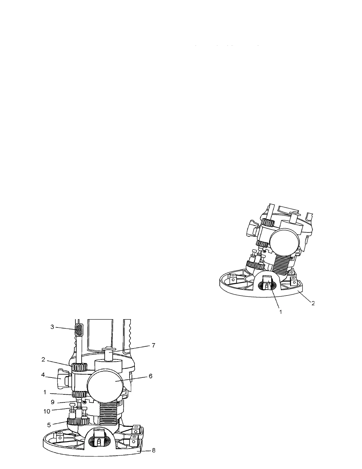
4. Loosen both height adjusting knobs (6) by turning
them counter-clockwise.
NOTE: Only loosen height adjusting knobs enough to
release the tension on the guide rods (7).
5. Slide router base (8) up or down to obtain the desired
depth of cut.
6. Re-tighten height adjusting knobs when the desired
cut depth is reached.
7. Push the depth stop quick release button and lower
depth stop rod until it contacts the step turret stop
screw (9). After releasing the quick release button,
finer adjustments can be made by turning the depth
stop rod.
8. Lock both the lower (1) and upper (2) depth stop lock
nuts against the router body to lock the depth stop rod
in place.
NOTE: Do not use pliers to tighten lock nuts. Turn lock
nuts by hand only.
9. Lock shortest step turret stop screw by tightening lock
nut (10).
NOTE: Do not over tighten lock nut.
10. Loosen both height adjusting knobs just enough to
allow router to freely slide up and down on the guide
rods.
11. Two additional depths can be pre-set in a similar way
setting the other two step turret stop screws to the
desired depth.
NOTE: To select pre-set plunge depth, simply rotate
the step turret until the correct turret stop screw is
aligned under the depth stop rod.
SETTING ROUTER BASE BEVEL
Bevel cutting with the cutting bit can be done with the
router base tilted to the desired angle.
1. Loosen both bevel adjusting locks (1) by pulling them
outward from the router base (2) (see Fig. 18).
2. Tilt router base to the desired angle.
NOTE: There are detents for locking the router base
at 0
o
, 15
o
, 30
o
and 45
o
. These are the four most
common angles for bevel cutting.
3. Lock both bevel adjusting locks by pushing them firmly
back into position against the router base.
4. Check bevel angle between router base and router bit
to ensure they are at correct angle.
5. Check router depth of cut and re-set the depth if
required.
NOTE: Depth of cut will usually have to be increased
after tilting the router base for bevel cutting.