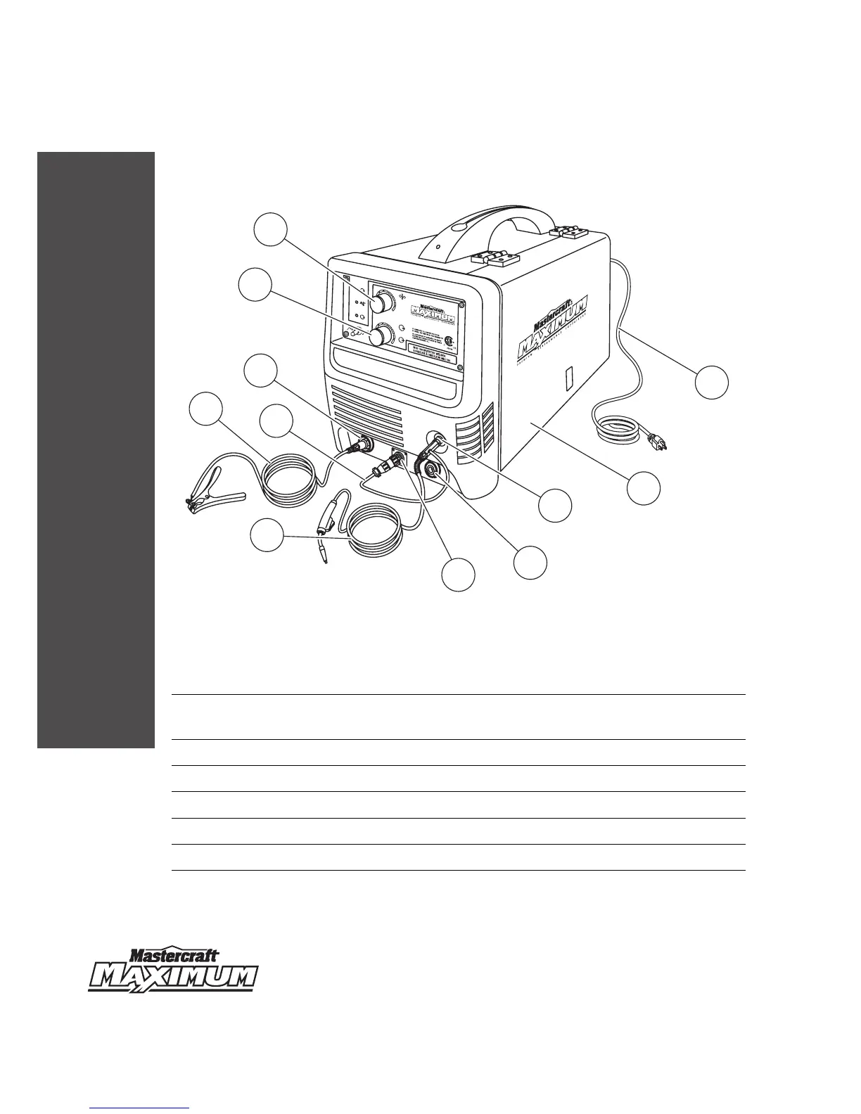
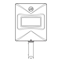
KEY PARTS DIAGRAM
9
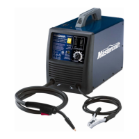
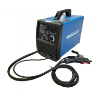
MIG 180 INVERTER WELDER 058-9306-4
No. Description No. Description
1
Voltage control (MIG mode) / Amperage
control (stick mode)
7 MIG gun trigger connection
2 Wire feed speed control 8 MIG gun cable
3 Power cord 9 Ground cable with clamp
4 Wire drive compartment door 10 MIG gun trigger cable
5 MIG gun connection 11 Ground cable connection
6 Electrode cable connection
MC-589306-01
GAS INER
9
9
3
4
5
6
7
8
WIRE
MIG
V
STICK
A
10
3
4
5
6
7
8
10
POWER
WARNING
WORK
V
A
STICK
MIG
2
5
4
3
6
7
8
9
10
11
FIL
AVERTISSEMENT
1
GAS INERTE
ARC
ARC
MARCHE
058-9306-4
INTENSITÉ
MIG 180 INVERTER WELDER
SOUDEUSE À ONDULEUR MIG 180