IMPORTANT INFORMATION
13
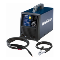
MIG 180 INVERTER WELDER 058-9306-4
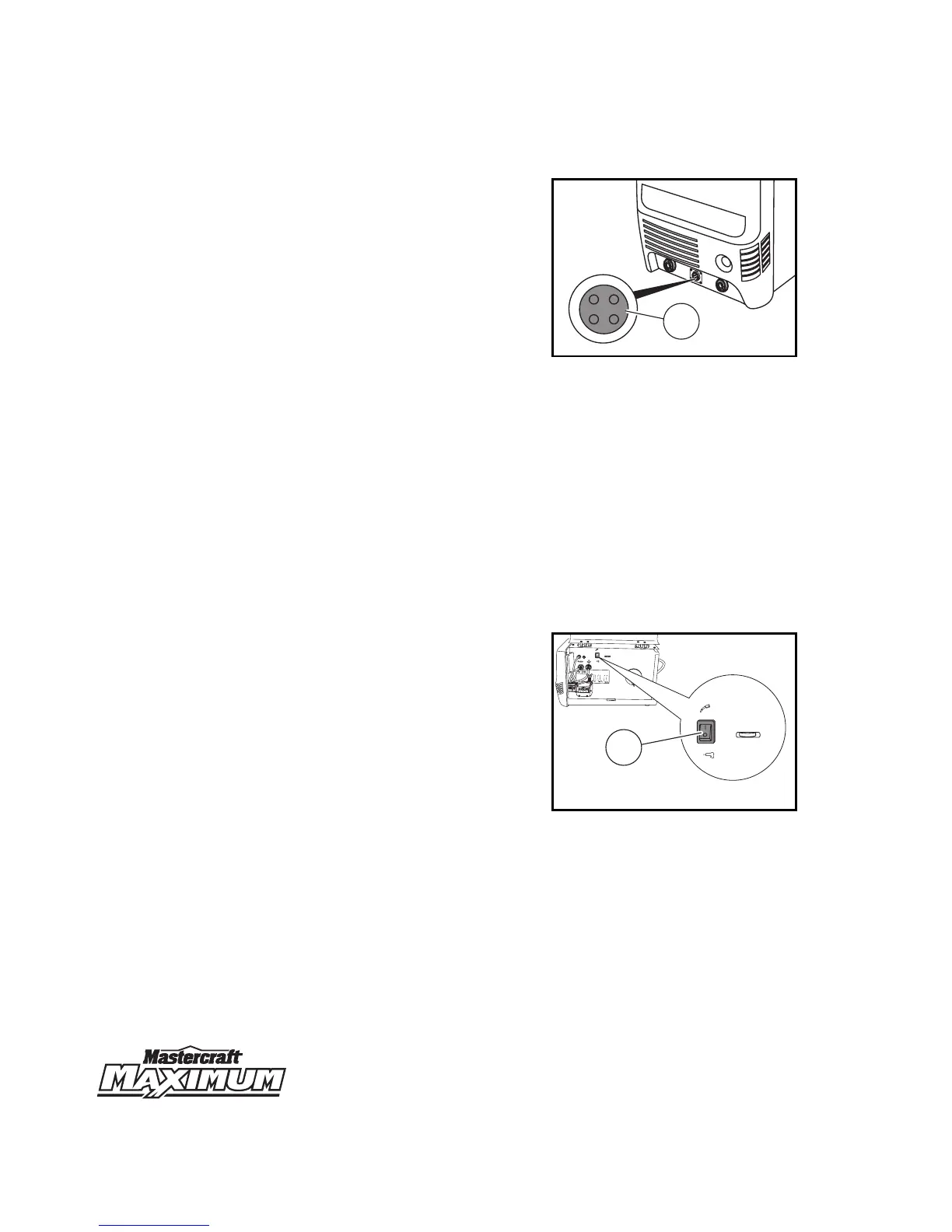
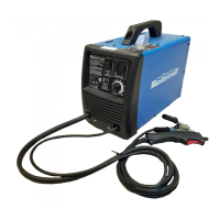
MIG gun trigger connection
This MIG gun trigger connection (1) is located
in the lower front panel and connects the 4-pin
quick connect plug of the MIG gun or the spool
gun (not included) with the welding unit.
Connections 1 and 2 are provided for the MIG
gun/spool gun and connections 3 and 4 are
provided for the wire feed motor.
Mode selector switch
This switch is located on the upper front panel of the welder and is used to select either MIG
welding mode or stick welding mode.
Power ON indicator
This indicator is located on the upper front panel of the welder and glows when the primary power
plug is connected to the power supply and the switch is turned ON.
Primary power switch
This switch is located on the back panel of the welder and enables to turn the welding unit ON or OFF.
Spool gun selector
The spool gun selector (1) is located inside the
wire compartment. This selector is switched to
spool gun mode when an optional spool gun
(not included) is being used, otherwise it stays
in the MIG mode. Refer to spool gun’s manual
for its connection instructions.
Thermal overload indicator
This indicator is located on the upper front panel of the welder and glows when the thermal overload
circuit is activated. The welding unit stops working during this period protecting the unit from any
damage. The cooling fan of the welding unit continues to work even if the welding unit is shut down
by the thermal overload circuit.
12
3
4
MC-589306-35
1
MIG 180 INVERTER WELDER
SOUDEUSE À ONDULEUR MIG 180
WARN
IN
G /
AV
ER
TI
S
SEM
E
N
T
E
L
ECTRIC
SHOCK
c
a
n
k
ill
U
N C
H
O
C
É
L
EC
TR
IQUE
p
e
ut t
u
er.
MOUING PAR
TS
c
a
n
ca
u
se i
n
j
u
ry.
LE
S
P
IÉC
E
S
MO
BILE
S
p
euvent c
a
us
e
r d
e
s
b
l
e
ss
ur
es.
•
W
e
l
di
ng wi
r
e an
d
dri
v
e part
s
m
ay
be
at
w
el
d
i
n
g
v
o
l
t
ag
e.
•
Keep
aw
a
y fro
m
m
o
v
i
ng p
ar
t
s
.
•
Ne
v
o
u
s
appr
oc
he
z
p
as
d
es
piè
ces
m
ob
i
l
e
s
.
•
M
ai
n
t
en
ez
t
o
us
l
es
co
uv
ercl
es,
p
an
neau
s
e
t p
orte
s
f
erm
és
et
s
o
l
i
dem
e
n
t
e
n
p
lac
e
.
•
Keep
al
l
do
o
rs,
c
overs
a
n
d p
an
el
s
cl
o
s
ed
a
n
d
s
ecu
r
el
y
i
n pl
ac
e
.
• Le
fi
l
d
e s
o
udu
r
e et
l
e
s
pi
èces
m
o
t
r
i
ces
s
o
n
t
peu
t
-ê
t
re
a l
a
tens
i
o
n de s
o
udag
e.
• N
e tou
ch
ez p
a
s
l
e fil
o
ules
parti
es
mo
t
r
i
c
e
s à m
a
in
s
n
ues
o
u
av
ec de
s
o
u
til
s
l
o
rs
que l
a det
en
t
e es
t s
o
u
s
,
p
r
es
s
i
o
n.
•
D
o
not
to
uch
wi
r
e
or drive parts
wi
t
h
b
ar
e h
a
n
d
s
or
to
o
l
s
w
hen
t
r
i
g
g
e
r
i
s
depr
e
ss
ed.
MIG
SPOOL GUN/PISTOLET À BOBINE
When normal MIG welding,
this switch should be turned in “MIG” positio
n.
when using spool gun
.
this switch should be in “
Spool gun” position.
Ce commutateur doit être placé à la position «
MIG »
si vous effectuez du soudage MIG normal
et à la p
osit
ion « SPOOL GUN »
si vous utilisez un pistolet à bobine
.
D
CEN
D
CE
N
FL
UX
COR
E
WIRE
FIL AVE
C ÂME
EN
FL
U
X
C
ou
r
a
nt
con
t
inu
po
la
ri
t
é no
r
ma
le
P
ol
a
rit
y
sw
it
c
h
se
t
tin
g
:
R
é
g
la
ge
du
c
o
mmut
a
t
e
u
r de polarit
é
:
D
i
r
e
ct
c
urrent
, e
lec
t
ro
d
e
nagat
i
ve
DC
E
P
DC
EP
M
IG
M
IG
D
i
rect cu
rren
t
,
el
ectro
de po
s
i
ti
ve
C
o
ur
an
t co
nt
in
u
, el
ectro
d
e
p
o
s
i
ti
v
e
P
o
l
ari
t
y
s
w
i
t
c
h
s
etti
n
g
:
Rég
l
a
g
e du
co
m
mu
tateu
r d
e
p
ola
ri
té
:
S
T
ICK
BAGUETTE
P
o
l
ari
t
y
sw
i
tch
se
ttin
g
:
R
é
glag
e
d
u c
om
mu
ta
t
e
u
r
d
e
p
o
larité
:
+
+
+
-
-
-
NO
GAS/P
A
S DE G
A
Z
G
A
S
/GA
Z
MIG
SPOOL GUN/PISTOLET À BOBINE
When normal MIG welding,
this switch should be turned in “MIG” position.
when using spool gun.
this switch should be in “Spool gun” position.
Ce commutateur doit être placé à la position « MIG »
si vous effectuez du soudage MIG normal
et à la position « SPOOL GUN »
si vous utilisez un pistolet à bobine.
1