OPERATING INSTRUCTIONS
31
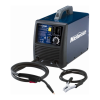
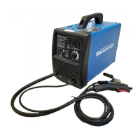
MIG 180 INVERTER WELDER 058-9306-4
There are two angles of the torch nozzle in relation to the work piece that must be considered when
welding.
4. Turn the wire feed speed control with
the other hand to its maximum position
and continue to hold onto the speed
control.
5. Pull the trigger (1) on the torch to start an
arc. Drag the torch toward the user while
simultaneously turning the wire feed
speed control counterclockwise
(fig 2G)
.
6. When the wire speed decreases, the sound that the arc makes will change from a sputtering
sound to a high-pitched buzzing sound. The correct setting is the point where the high-pitched
buzzing sound is achieved. Use the wire feed control to slightly increase or decrease the heat
and penetration by selecting higher or lower wire feed settings.
Repeat the above steps 1-5 if a new wire speed, a different diameter wire or a different type of
welding wire is selected.
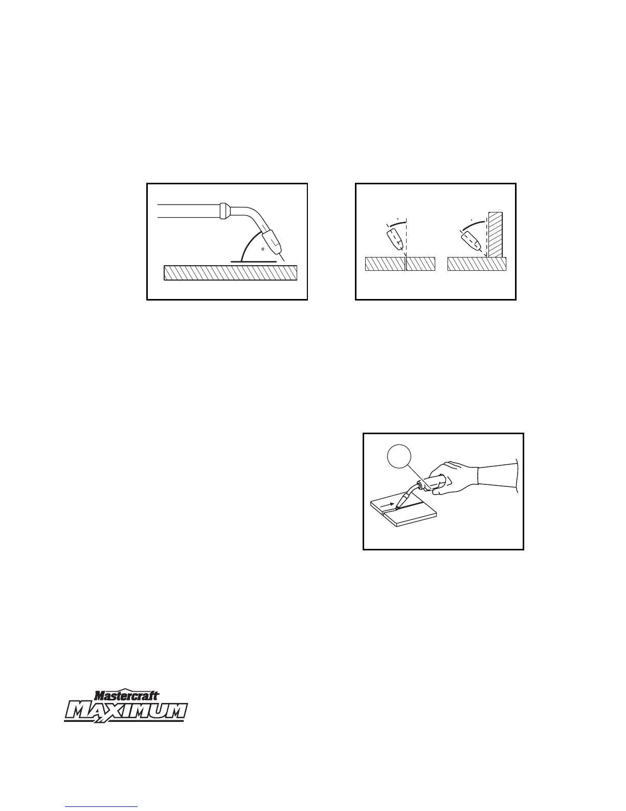
Angle A (60 degrees) Angle B (30-45 degrees)
• Angle A is the angle between the nozzle
and the work piece and can be varied, but
in most cases the optimum angle will be
60 degrees (the point at which the torch
handle is parallel to the work piece). If
angle A is increased, penetration will
increase, and if decreased penetration
will decrease
(fig 2E)
.
• Angle B is the angle between the
perpendicular of the work piece and the
nozzle and can be varied to improve the
visibility of the arc in relation to the weld
puddle and to direct the force of the arc
(fig 2F)
.
60
fig 2E
MC-589306-40
30
45
fig 2F
MC-589306-41
MC-589306-42
1
fig 2G