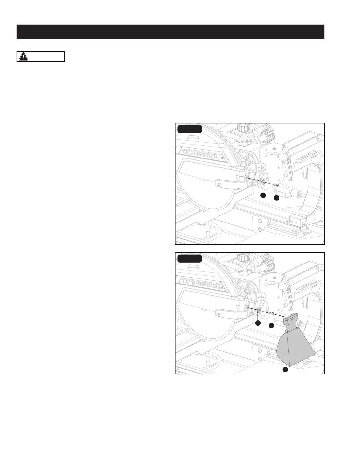
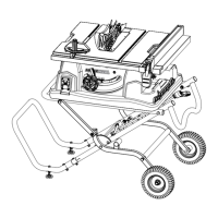
FIG. 11A
INSTALLING THE SPLASH GUARDS
(Fig. 11A-11C)
• Remove M5 x 12mm cross screw (ee) and big at washer
5 (ff) from the motor head assembly.
• Attach the rear splash guard (O) to the back of the blade
guard with the big at washer 5 (ff) and M5 x 12 cross
screw (ee).
• Place outer ange (aa) onto the spindle (cc). The ats on the outer ange align with the ats on the spindle. Install with
the cupped side of the outer ange facing the tile saw blade.
• Place spindle nut (ZZ) on spindle (cc). Press and hold the spindle lock (YY) in. Wrench (J) tighten spindle nut securely.
Release the spindle lock.
• Close the blade guard (XX), and use the guard knob (WW) to secure it.
Page 20
ASSEMBLY
CAUTION: The tile saw is equipped with two water nozzles (dd) to wet the tile saw blade during operation. Make
sure holes in nozzles face the tile saw blade and that tile saw blade is positioned between the two nozzles.
ee
ff
ee
O
ff
FIG. 11B