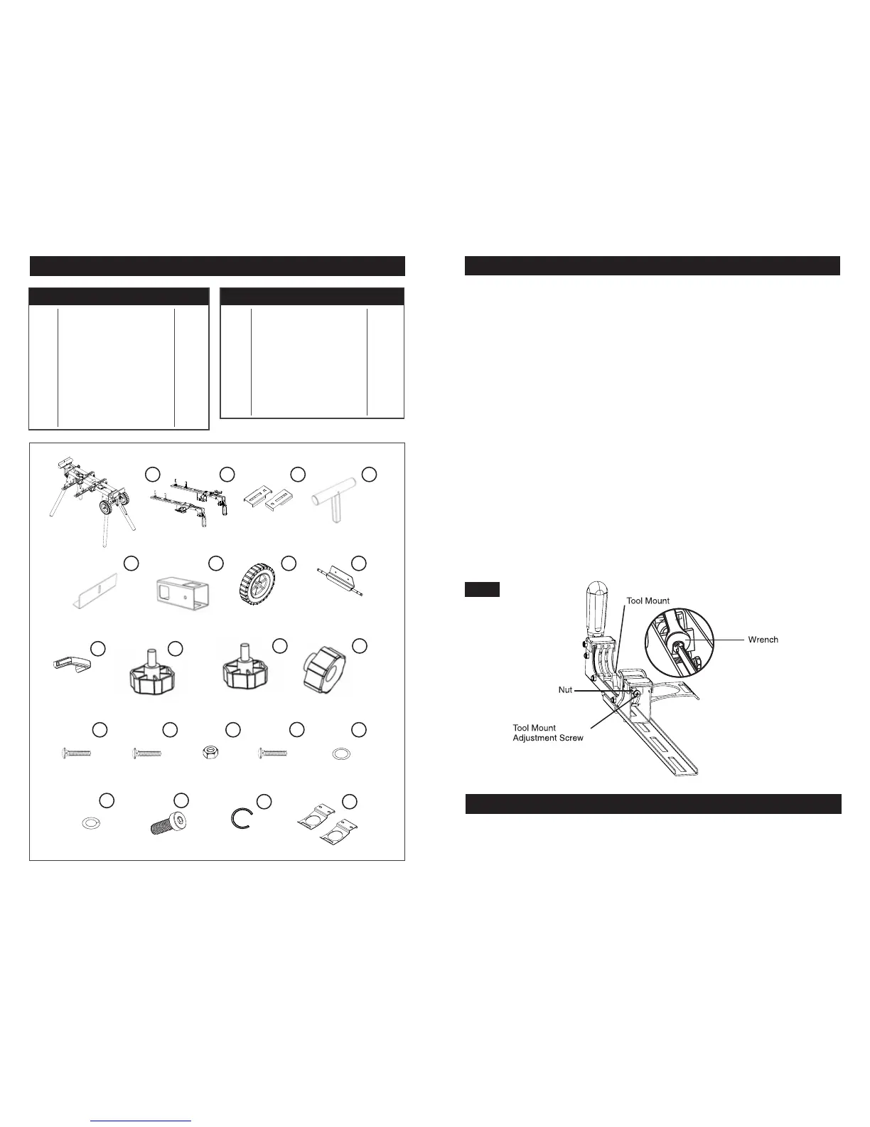
PARTS LIST
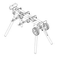
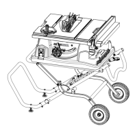
MITER SAW STATION
RAPID CLAMP TOOL MOUNT
OFFSET MOUNTING BRACKETS
MATERIAL SUPPORT
WORK STOP
MATERIAL SUPPORT RECEIVER
WHEEL
AXLE PLATE
HANDLE
KNOBS M8*35
KNOBS M8*25
1 pcs
2 pcs
2 pcs
2 pcs
2 pcs
2 pcs
2 pcs
1 pcs
1 pcs
2 pcs
4 pcs
1
2
3
4
5
6
7
8
9
10
11
KNOB NUTS M6
CARRIAGE BOLT M8*55
CARRIAGE BOLT M8*20
NUT M8
CARRIAGE BOLT M8*60
WASHER #8
SPRING WASHER #8
BOLT M8*25
C-CLIP
STORAGE HANDLES
2 pcs
2 pcs
6 pcs
14 pcs
4 pcs
14 pcs
14 pcs
4 pcs
4 pcs
2 pcs
12
13
14
15
16
17
18
19
20
21
PART # DESCRIPTION QTY
1
5
2 3 4
6 7 8
9
10
11
12
13 14 15
19
20 21
16
17
18
ASSEMBLY INSTRUCTIONS
TOOL MOUNT ADJUSTMENT SCREW
TO ADJUST
Most plastic tool mounts are designed to fit snugly over the stand rails. With the locking levers in
the lowered (locked) position, you should not be able to remove the saw and tool mount
assembly from the rails. If the saw and tool mount can be removed from the rails when the levers
are locked, the tool mount adjustment screws need to be tightened. If the saw and the tool
mount assembly will not fit over both rails, the bracket adjustment screws needs to
be loosened.
NOTE: The saw should be removed from the tool mounts before attempting to tighten or
loosen the tool mount adjustment screws.
Figure 13.
1. Use a wrench to slightly loosen the nut.
2. Turn the screw with a Phillips screwdriver. Rotate clockwise if the tool mount assembly needs
to be tightened or counterclockwise if the assembly needs to be loosened.
3. Install the tool mount on the Contractor Miter Saw Station rails and lower the locking
lever to check the adjustment.
4. When the correct position is achieved, tighten the nut with a 10mm open-ended wrench
to secure.
5. Repeat steps 1 through 4 to attach the second tool mount.
FIG 13
GENERAL MAINTENANCE
Avoid using solvents when cleaning plastic parts. Most plastics are susceptible to damage
from various types of commercial solvents and may be damaged by their use. Use clean cloths
to remove dirt, dust, oil, grease, etc.
Page 3 Page 12
PART # DESCRIPTION QTY