INSTALLING THE METAL CUTTING DISC
GUARD – Cont’d
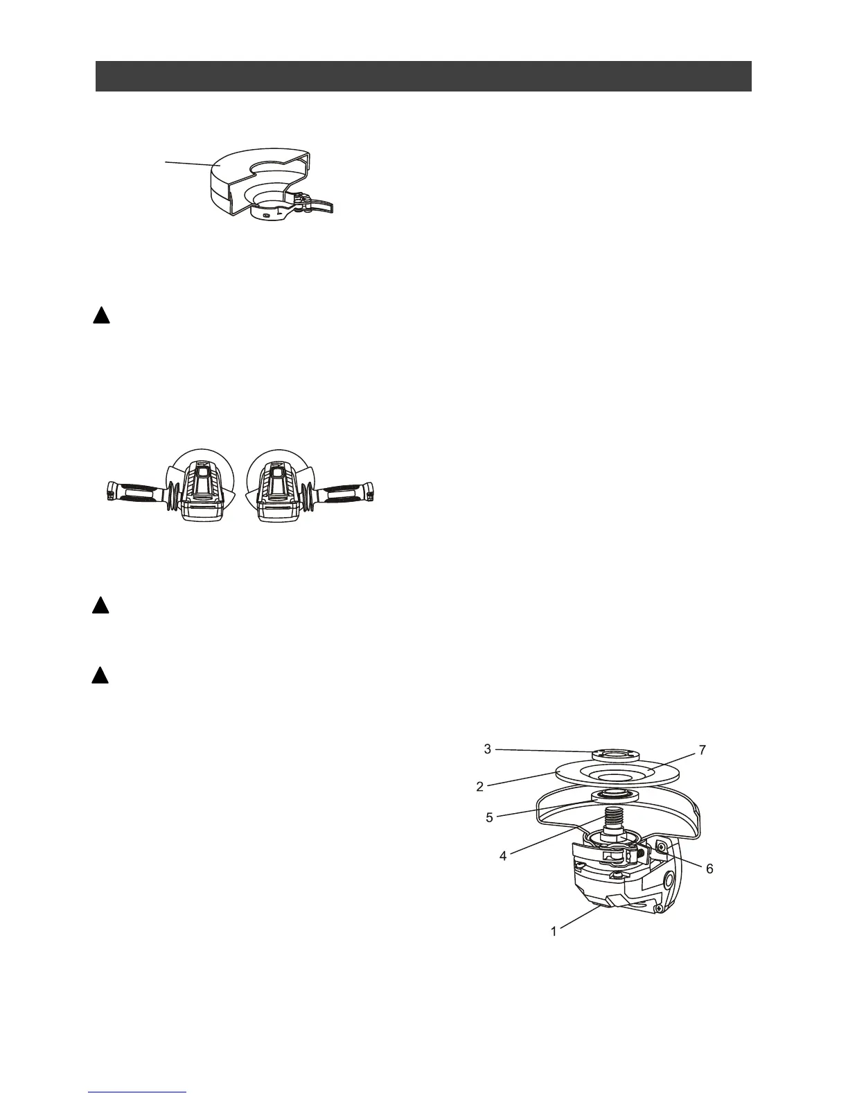
POSITIONING THE GUARD
WARNING: The guard must be
positioned correctly to protect the operator.
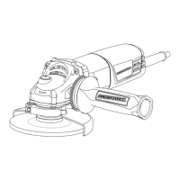
Guard placement depends upon which side
of the tool the auxiliary handle is used, to
afford the greatest protection for the user.
Rotate the guard to the correct position as
noted in Fig. 4 or 5 below.
CHANGING A GRINDING DISC
WARNING: Use the correct size
grinding disc. Never use a grinding disc
thinner than 7/64" (2.5 mm).
WARNING: Never use a grinding disc
with a rated speed of less than (11,800 RPM).
A grinding disc with a rated speed of less
than 11,800 RPM can break and fly apart.
1. Lock the disc guard onto the spindle
housing.
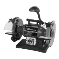
2. Depress the spindle lock button (1) and
rotate the grinding disc (2) until the spindle
locks (Fig. 5).
3. Grasp the grinding disc and rotate the
grinding disc in a counter clockwise
direction. Once the grinding disc and outer
disc flange (3) are loose, continue to turn
the outer disc flange counter clockwise by
hand until it is removed from the spindle
(4).
4. Remove the grinding disc from the spindle.
NOTES:
a) If the outer flange cannot be loosened by
hand, use the wrench provided.
b) DO NOT remove the inner disc flange (5).
5. Make sure the flats on the inner disc flange
are engaged with the flats on the spindle
(6).
6. Place the grinding disc over the spindle
with the concave side of the disc (7) facing
outward.
7. Screw the outer disc flange onto the
spindle with the flat side of nut facing away
from the grinding disc. Tighten to finger
tight only.
NOTE: Make sure the raised small diameter
portion of both the inner and outer disc flanges
are fitted into the hole in the grinding disc.
8. Depress the spindle lock button and rotate
the grinding disc clockwise until the spindle
locks.
9. Grasp the grinding disc and turn it
clockwise to securely tighten the grinding
disc and outer flange onto the spindle.
NOTE: You may also tighten the grinding disc
and outer flange onto the spindle using the
wrench provided. The blade wrench is stored
inside the auxiliary handle (see Page 13).