INSTALLATION
EN / Chargemaster1 12/35-3, 12/50-3, 24/20-3 & 24/30-3 / August 2009 11
negative post of the battery bank or the ground side of a
current shunt. Do not use the chassis frame as the
negative conductor. Tighten securely. The positive battery
cable must be fused and connected to the positive post of
the battery bank.
Main charge outputs 1, 2 & 3
Model Chargemaster Recommended charger
fuse
12/35-3 40A
12/50-3 63A
24/20-3 32A
24/30-3 40A
The fuse with the fuse-holder is available from your local
Mastervolt distributor or Customer Service Representative,
see chapter 9 Ordering information.
4.3.3 Battery capacity
The minimum required battery capacity is as follows:
Model Chargemaster Minimum required battery
capacity
12/35-3 70-350Ah
12/50-3 100-500Ah
24/20-3 50-250Ah
24/30-3 70-350Ah
4.3.4 AC safety grounding
WARNING!
The ground wire offers protection only if the
cabinet of the Chargemaster is connected to
the safety ground. Connect the ground
terminal (PE / GND) to the hull or the chassis.
CAUTION!
For safe installation it is necessary to Insert a
Residual Current Device (earth leakage
switch) in the AC input circuit of the
Chargemaster.
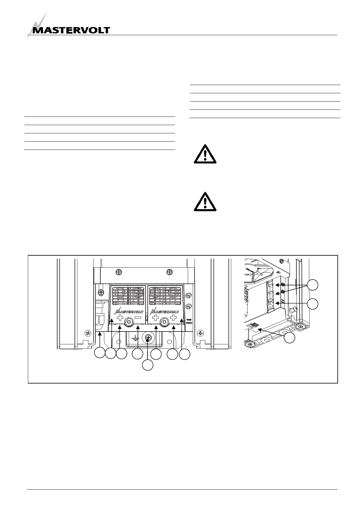
4.4 OVERVIEW CONNECTION COMPARTMENT
Figure 5: Overview connection compartment
1. Cable gland for AC-wiring
2. Isolation caps for DC connections
3. Positive terminal charge output 1
4. Common negative output terminal
5. Common ground connection
6. Positive terminal charge output 2
7. Positive terminal charge output 3
8. MasterBus connectors
9. Temperature sensor jack
10. DIP switches
2
3
4
6 7 2
5
10
9
8
 Loading...