Do you have a question about the Mastervolt chargemaster plus 12/75-3 and is the answer not in the manual?
Guideline for safe and effective operation and maintenance of the ChargeMaster Plus.
Specifies applicability of manual to standard versions and specific models.
Explains safety instructions and warnings marked by pictograms.
Location and importance of the identification label for technical information.
Mastervolt's disclaimer regarding consequential damage and manual errors.
General safety and operating instructions for the ChargeMaster Plus.
Warning about explosive gases from lead-acid batteries and precautions.
Precautions for personal safety when working near batteries.
Warnings related to charging and handling of batteries.
Recommendations for placing the charger away from the battery.
Precautions for connecting and disconnecting DC output clips.
Step-by-step guide for connecting the charger in a vehicle.
Step-by-step guide for connecting the charger with the battery outside a vehicle.
Steps for preparing the battery and charger before initiating charging.
Guidelines for proper grounding of the battery charger.
Disclaimer regarding use in life support systems.
Information about the product guarantee and its limitations.
Instructions for the proper disposal of the product as WEEE.
Overview of the ChargeMaster Plus's features like Li-ion compatibility, multi-chemistry, multi-battery.
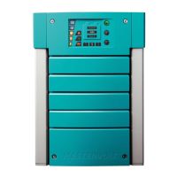
Description of the front panel display and controls for charger operation.
Explanation of the 3-level status display and LED indicators.
Procedure for activating and deactivating the ChargeMaster Plus using the MODE switch.
Detailed explanation of status display states and corresponding LEDs.
Explanation of how output power is indicated on the status display.
Details error codes indicated by LEDs and recommended actions.
Instructions for unpacking, checking contents, and verifying battery voltage.
Stipulations for installation environment, temperature, and humidity.
Guidelines and warnings for DC and AC wiring, including safety grounding.
Recommendations for battery capacity and following manufacturer instructions.
List of necessary parts and tools for installing the ChargeMaster Plus.
Diagram and labels for the connection compartment terminals.
General warnings and notes regarding electrical connections.
Detailed step-by-step instructions for mounting and connecting the unit.
Procedures for commissioning the unit after installation, including settings.
Instructions for safely removing the ChargeMaster Plus from operation.
Guidelines for storing and transporting the product.
Reference to installation chapter for re-installation procedures.
Guidelines for DC wiring, including cable cross-sections and colors.
General warnings and notes for electrical installation work.
Guidelines for AC wiring, including wire cross-sections and colors.
Instructions for AC safety grounding and RCD/Breaker installation.
Recommended battery capacities for different ChargeMaster Plus models.
List of necessary parts and tools for installing the ChargeMaster Plus.
Diagram and labels for the connection compartment terminals.
Schematic illustrating the general placement of the ChargeMaster Plus in a circuit.
General advice for commissioning, including resetting factory settings.
Step-by-step process for commissioning the charger, including polarity checks.
Procedure for commissioning the ChargeMaster Plus on a MasterBus network.
Instructions for safely removing the ChargeMaster Plus from operation.
Guidelines for storing and transporting the product.
Explanation of DIP switch settings for configuring the charger.
Configuration options via the MasterBus network.
Explanation of DIP switch settings for configuring the charger.
Settings for MasterBus communication modes (Smart on, Always on).
Setting to limit input current to protect against overload.
Configuration for integrating a MasterShunt for battery data.
Compatibility and configuration for Li-ion MLi Ultra batteries.
Option to exclude unused outputs from sending alarm messages.
Overview of monitoring parameters for charger and battery status.
List of alarm values, meanings, and adjustable ranges.
Menu showing maximum readings for charger and outputs.
Parameters configurable via MasterBus network, including language and battery type.
Configuration of events and actions within the MasterBus network.
Defining the ChargeMaster Plus as an event source for other devices.
Configuring the ChargeMaster Plus as an event target for other devices.
Description of the BULK, ABSORPTION, and FLOAT charging stages.
Description of the pre-float stage in the charging algorithm.
Explanation of how temperature affects charge voltage and the sensor's role.
How the charger automatically detects and charges flat batteries.
Configuration for Output 3 as a 10A starter battery charger.
Configuration for Output 3 as a starter battery charger.
Configuration for Output 3 to work with an alternator as a VSR.
Configuration for Output 3 to follow main battery charging settings.
Configuration for Output 3 to follow main charging and work with alternator.
Configuration for Output 3 as a 12V constant voltage charger.
Configuration for Output 3 as a 24V constant voltage charger.
Configuration for Output 3 as a 12V 3 step+ charger for specific battery types.
Instructions for cleaning and general maintenance of the ChargeMaster Plus.
Information on how failures are indicated and general protection features.
How to access historical data via MasterBus.
Instructions for safely removing the ChargeMaster Plus from operation.
Guidelines for storing and transporting the product.
Technical specifications for the 12V ChargeMaster Plus models.
Technical specifications for the 24V ChargeMaster Plus models.
Part numbers and descriptions for MasterBus installation components.
Part numbers and descriptions for miscellaneous items like fuses and sensors.
| Input Voltage | 90 - 265 VAC |
|---|---|
| Output Voltage | 12 VDC |
| Output Current | 75 A |
| Efficiency | > 90% |
| Number of Outputs | 1 |
| MasterBus compatible | Yes |
| Battery Types | Gel, AGM, Lithium |
| DC connection | M8 |
| Protection | Short circuit, Overload, Over temperature |
| Charging Stages | 3 (Bulk, Absorption, Float) |
| Temperature range (ambient) | -20°C to +60°C |
| Operating Temperature | -20°C to +60°C |