Position the positive and negative cables next to each
other to limit the electromagnetic field around the cables.
The negative cable should be connected directly to the
negative post of the battery bank or the load side of a
current shunt. Do not use the chassis frame or hull of the
ship as the negative conductor. Tighten the DC
connections securely (15 - 20 Nm / 130 - 175 In-Lbs.). The
positive battery cable must be fused and connected to the
positive post of the battery bank. Fuse rating depends on
the applied cable cross section.
5.3.3 AC safety grounding
WARNING
The ground wire offers protection only if the
cabinet of the Mass Combi Ultra is connected to
the safety ground.
The ground stud (M6) is positioned at the left side of the
cabinet, see page 2, position 12. Connect the earth
terminal (PE / GND) to the hull or the chassis with a
minimum 10 mm².
In some applications automatic connection between the
neutral conductor (N) and earth (PE / GND) is not required
or acceptable. Therefore the automatic connection
between the neutral conductor (N) and earth (PE / GND) is
disabled by default.
For safe installation it is necessary to insert a Residual
Current Device (earth leakage switch) of 30 mA in the AC
in and outputs of the Mass Combi Ultra. Refer to local
regulations on these issues!
5.4 Things you need
Make sure you have all the parts you need to install the
Mass Combi Ultra:
Mass Combi Ultra (included).
Battery temperature sensor with cable and plug
(included).
AC wiring. Double insulated three wire cable with wire
colours according to the locally applicable standards.
The applicable length and wire diameter depend on the
electrical installation. See section 5.3.1.
DC-wiring to connect the DC connections of the Mass
Combi Ultra to the DC-distribution; see section 5.3.2.
DC-fuse holder with a DC-fuse, to be integrated in the
positive DC-cable. For specifications see section 5.3.2.
Screws / bolts (Ø 6 mm) (with plugs) to mount the
cabinet to a surface. Use mounting materials which are
suitable to carry the weight of the Mass Combi Ultra.
Batteries. Refer to chapter 8 for specifications.
Appropriate and reliable cable terminals, cable lugs,
battery terminals and cord end terminals.
We recommend as a minimum tool kit:
Socket wrench 13 mm to fix the DC-input (battery)
cables.
Flat blade screw driver 1.0 x 4.0 mm to fix the screw
terminals.
Tools to fix the screws / bolts (Ø 6 mm) with plugs to
mount the cabinets to a surface.
Philips screw driver to open the connection area of the
Mass Combi Ultra.
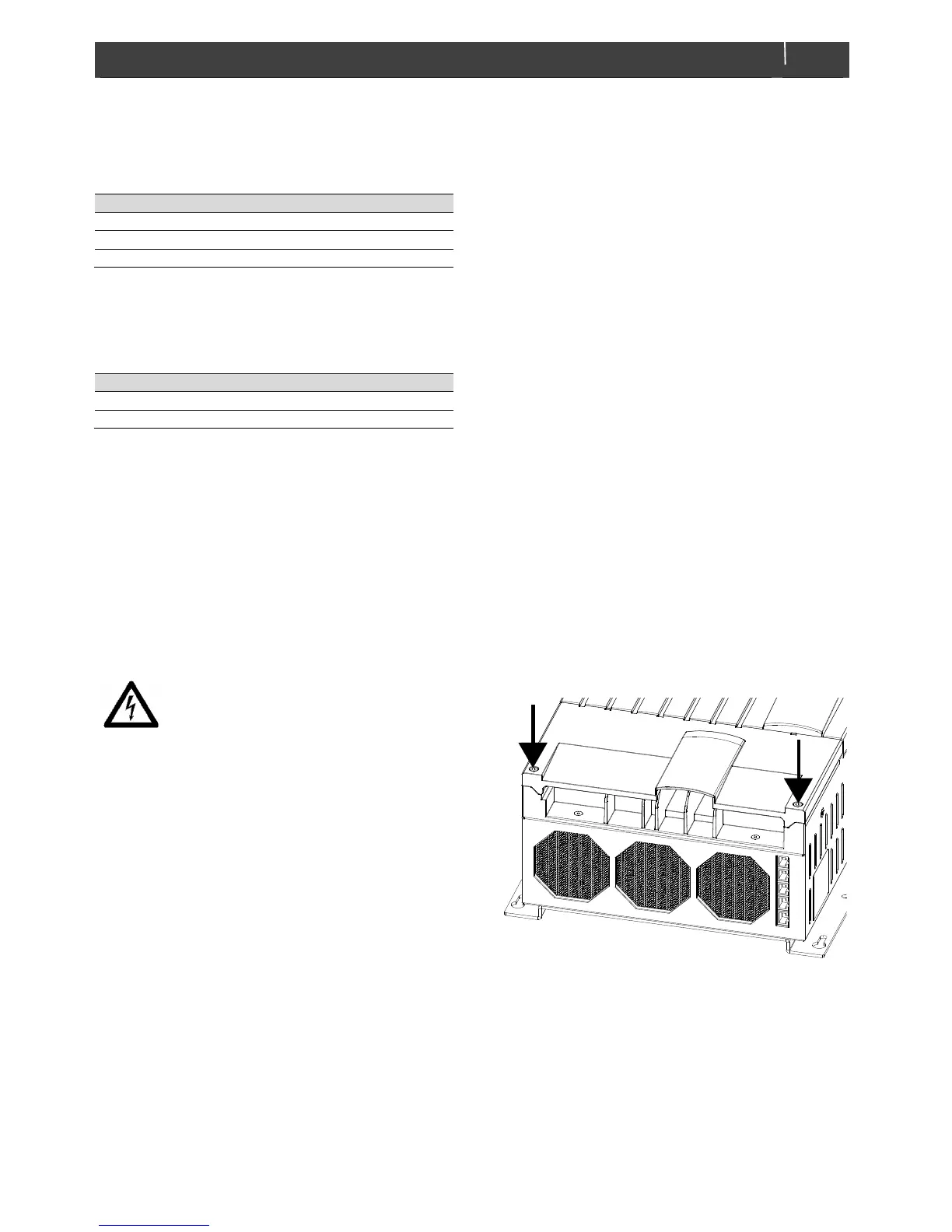
5.5 Removal of the front lid
Figure 5-2: Removal of the front lid
Steps:
1 Loosen the two screws that secure the front cover
plate.
2 Lift the front cover plate from the cabinet; see
figure 5-3.

 Loading...


