INSTALLATION
10 Copyright © 2008 Mastervolt / October 2008 / WHISPER 15/20 ULTRA - Three Phase / US
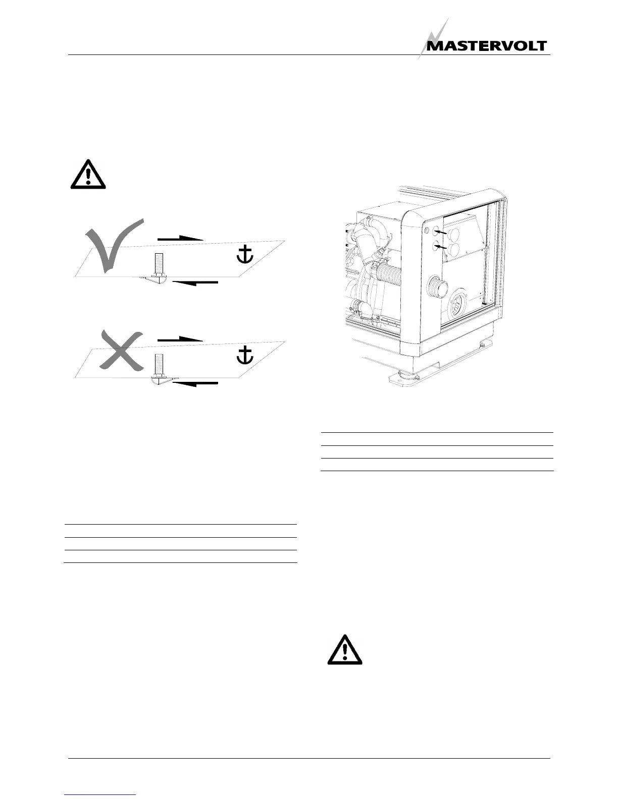
3 INSTALLATION OF THROUGH HULL FITTING
It is good practice for yachts to use a hull inlet fitting with
an integrated strainer (water scoop). For propulsion
engines in motorboats the water scoop is often mounted
against the sailing direction to induce more water intake
for cooling.
This should not be done in the case of a
generating set! When sailing at higher
speeds, water will be forced into the inlet and
your generating set will overflow!
Fig. 9 Installing water intake
On motorboats and on sailing boats the water scoop for a
generating set should be fitted with the opening faced
backwards to prevent water being forced in during sailing.
4 WATER STRAINER
Use an appropriate water strainer with connections of the
following dimensions:
Model Inner dimensions
Whisper 15 Ultra Three Phase 3/4" (19 mm)
Whisper 20 Ultra Three Phase 1" (25.4 mm)
Install the water strainer in a well accessible position,
(refer to fig. 8, ref. 6) 5 cm above the waterline.
5 SIPHON BREAKER (AIR VENT)
When the point of water injection is below the waterline,
then -when the engine is stopped -there is a risk that the
cooling water may enter the engine as a result of
siphoning. To avoid this happening, the generating set is
designed to accommodate a siphon breaker (air vent). In
the standard delivery the connections are bypassed. See
figure 10
Fig. 10: Bypassed siphon breaker connections
Hoses with the following inner diameter should be used:
Model Inner dimensions
Whisper 15 Ultra Three Phase 3/4" (19 mm)
Whisper 20 Ultra Three Phase 1" (25.4 mm)
If the generating set cannot be mounted such that the
bottom of the generating set is placed above the waterline,
an air vent must be installed. See figure 11
Extend the water hose of the by-pass 60 cm above
waterline and install an air vent. Ideally, the air vent should
be mounted above the yacht keel center line (i.e. to
minimize the influence of swaying on the water intake).
Fast motorboats will lay deeper when sailing at large
speed and can cause pressure on the waterinlet. This
should be avoided to prevent fleeding the engine.
If the air vent is clogged the water hoses will
not be vented when the generating set has
stopped and water can be forced into the
engine. This leads to immediate engine
problems and eventually severe damage!
DAMAGE CAUSED BY THE INGRESS OF WATER IN
THE ENGINE IS NOT COVERED BY GUARANTEE
SAILING DIRECTION
SAILING DIRECTION
FLOW DIRECTION
FLOW DIRECTION
 Loading...