INSTALLATION
US / WHISPER 15/20 ULTRA - Three Phase / October 2008 / Copyright © 2008 Mastervolt 15
If the generating set and the exhaust system have been
installed correctly, neighbouring boats will not be disturbed
by generating set noise, With the "super silent" exhaust
system, generating set noises are almost inaudible. For
optimal noise reduction, the sea water outlet from the
exhaust/water separator (center outlet on the unit) should
be installed below the water level to eliminate noisy
splashing of the effluent sea water.
The through-hull outlet for the exhaust fumes should not
direct the fumes directly toward the water surface as this
will cause excessive noise (ref. to figure 19).
Do not direct the outlet directly toward the
water surface.
Figure 19: Outlet direction
1.5.4 Digital Diesel Control system (12 Volt)
1 DIGITAL DIESEL CONTROL SYSTEM
The electrical control system is standard in 12 Volt with
negative earth. Non- earth return is available as an option
for aluminium vessels to prevent corrosion.
All electrical wiring has been prepared on the generating
set to the control panel prior to despatch from the factory.
The engine is controlled by a very advanced
microprocessor based system: Digital Diesel Control.
The “black box” containing the microprocessor is located
on top of the alternator.
A local control panel is on the generating set.
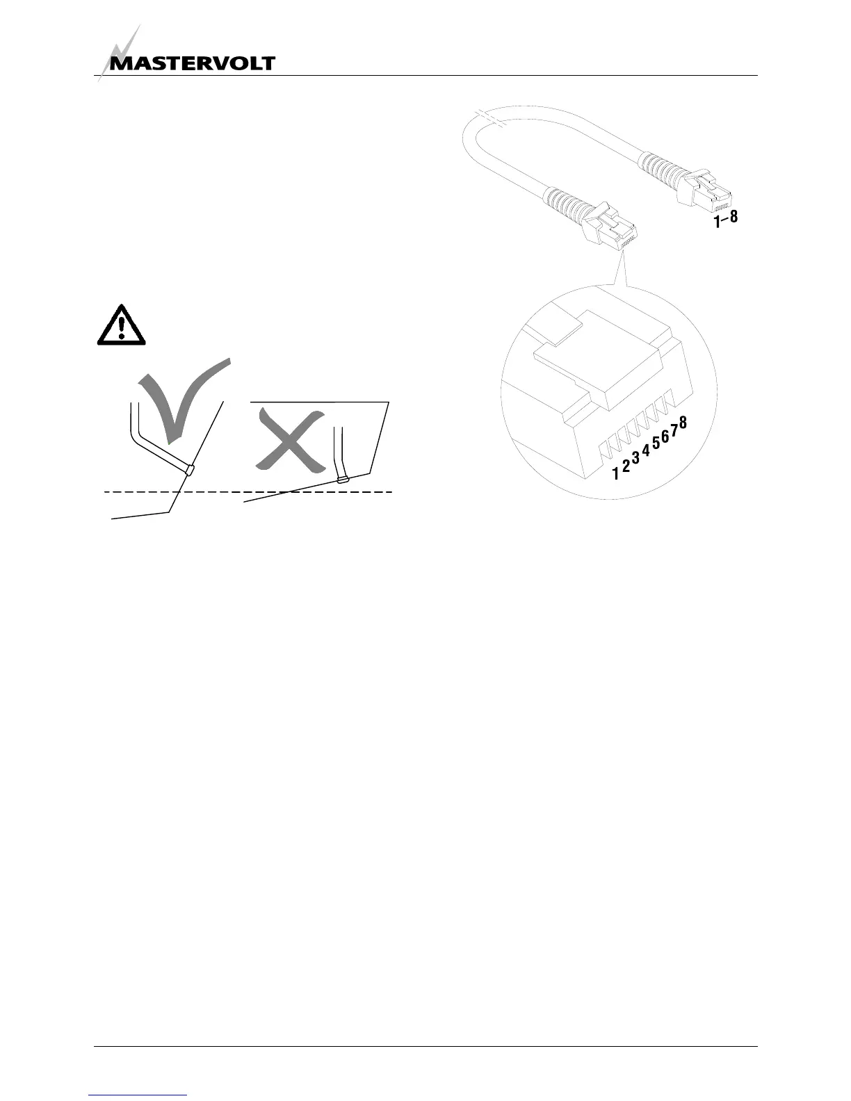
Remote control
A remote control panel also containing a microprocessor is
in the delivery. A 15 m intermediate 8-pole communication
cable is in the standard supply as well (refer to fig. 20). If
necessary an optional longer (up to 30m / 100ft)
intermediate cable can be connected if the standard length
does not suit the required distance. When a longer
distance than 30m / 100ft is required, consult the
Mastervolt service department for advice.
Fig. 20 Remote control cable
One can mount the control panel after drilling a hole in the
dashboard using the plastic cover. Refer to the
dimensional drawing in paragraph 3.5. The panel without
the plastic cover fits the Mastervision modular panel
system.
More remote control panels (slave panels) can be put in
parallel by using the modular connectors on the back of
the units. As a slave one can use the same panel offering
all functions again. It is also possible to use an old or new
type slave panel only to start and stop the generator.
Old type remote panels and system panels (like the
System Manager AC + Whisper or the CSCP4) can be
connected by means of the green connector.
Pay attention to the colour codes as indicated in fig. 21
when fitting cable to the green connector. Some software
versions in old system panels (supplied before May 2004)
could conflict with the software in the DDC and an update
of the software of the system panel could be necessary.
When this is the case consult to the Mastervolt service
department for advice.
When using the factory settings, installation is very simple:
just plug the remote cable into the remote and the
generator is ready to use. Refer to fig. 21.
OK!
WRONG!
 Loading...


