INSTALLATION
16 Copyright © 2008 Mastervolt / October 2008 / WHISPER 15/20 ULTRA - Three Phase / US
WIRING COLOURS
RED
GREEN
BROW N
YELLOW
PI NK
PURPLE
BL UE
WHI TE
GRE Y/ P I N K
GRE Y
RED/ BLUE
BLACK
MAX. 150 mA
WARNING RELAY
REMOTE CABLE
REMOTE CABLE
2
1
5
4
3
8
7
6
11
10
9
12
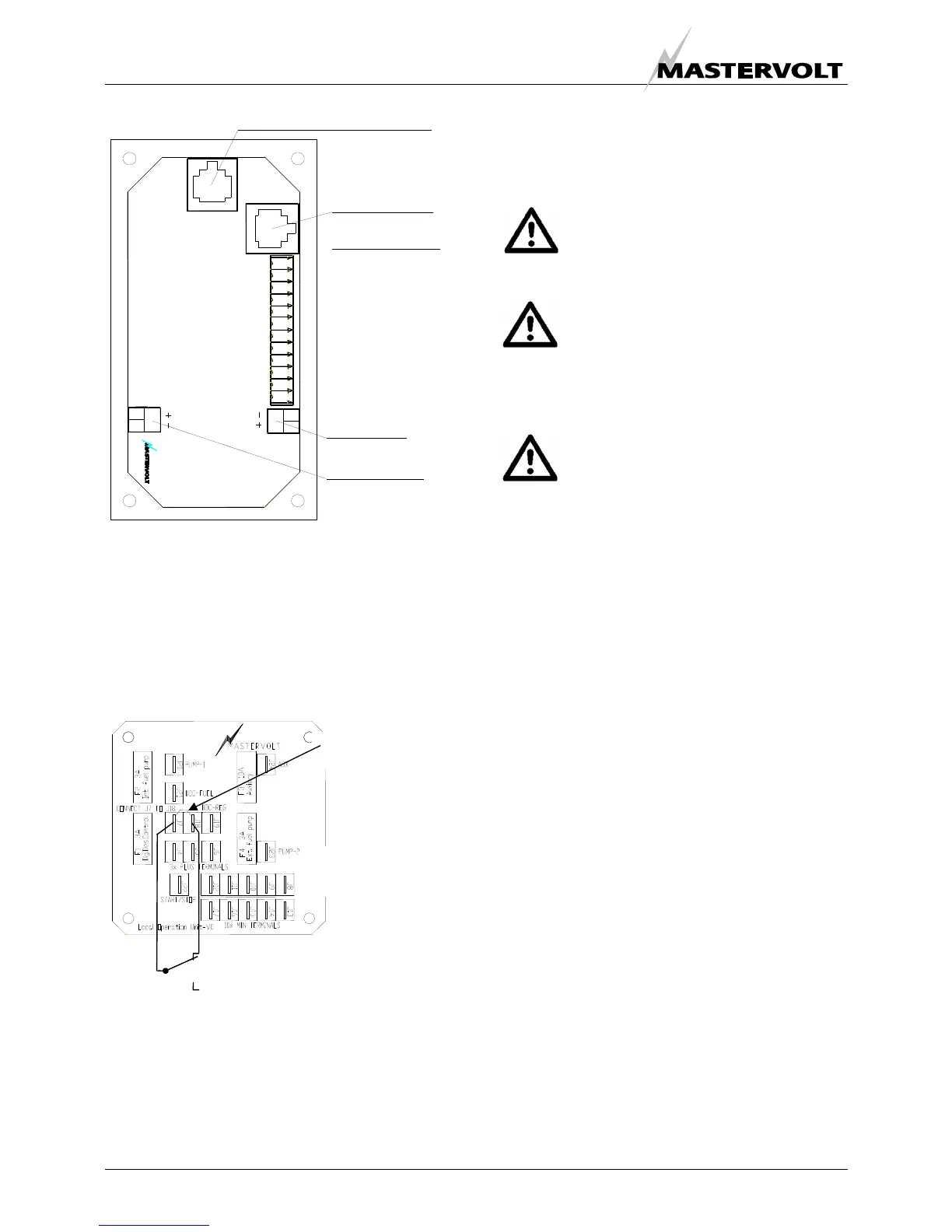
SENSE BAT. 2
121110987654321
Whisper Remote Panel
WRP/ 2
J3
Fig. 21 Remote box terminals
Acoustic alarm or warning lamp
One can connect an external max.150 mA relay to
generate an acoustic warning or applying a warning lamp
etc. Be aware of polarity as some relays has a diode
inside and should be connected plus to plus en minus to
minus as indicated. Refer to fig. 21.
Connection for emergency stop / fire alarm switch
Fig. 22: Connection for emergency stop / fire alarm switch
To connect an emergency stop button or to stop the
generator automatically in case of a fire alarm, you can
use the bypass connection between fastons J7 and J18 on
the backside of the local control panel. See fig. 22. To do
so, remove this bypass connection and then replace it by
an emergency switch or a potential free fire alarm switch
with normally closed contacts
Automatic start/stop
Mastervolt cannot be held responsible for
damage caused by the unattended running
generator using the auto-start/stop mode or
interval mode
Using the auto-start/stop (interval) mode the
generator can start unexpectedly. When
working on the electrical system, the 3 Amp
fuse must be removed from the control panel
and the battery plus cable must be removed
from the battery.
In the delivery are warning stickers to stick on
several parts of the electric installation
(transfer switch, distribution box, etc.) to warn
for automatic start)
The Mastervolt Digital Diesel Control system offers several
options for automatic starting and stopping.
Access to this menu and other menus could be blocked.
For blocking and setting up this options refer to the
APPENDIX of the DDC users manual.
One of these options is to monitor a second battery (not
being the starter battery) to start the generator
automatically when the voltage of this battery drops below
a certain setting.
Other names for this second battery are “auxiliary battery”,
“service battery”, ”users battery” or “consumers battery”.
We will refer to this battery as “the second battery”(BAT2).
In some menus the starter battery could be indicated as
“the first battery” (BAT1).
A sense wire to monitor the second battery should be
connected (attention polarity!) to the connector on the
back of the remote panel. Refer to fig. 21. The sense wires
must be connected directly on the second battery before a
main switch and be protected by a 3 Amps fuse.
(Monitoring the generator starter battery does not require
an extra sense connection)
Settings
When one want to apply other settings than the factory
settings refer to the DDC users manual, especially to the
APPENDIX.
Remove bypass
between J7 - J18
Normal operation
Alarm / emergency
local control panel
(rear view)
 Loading...


