INSTALLATION
10 Copyright © 2009 Mastervolt / July 2009 / WHISPER 6/8/11 / US
1.5.3 Exhaust system
Water is injected in the exhaust system of the generating
set. In this way the cooling water that has passed the heat
exchanger is mixed with the exhaust gases. Temperature
and volume of the gases are thereby reduced
considerably, so that a rubber exhaust hose can be used
and the level of noise is reduced as well.
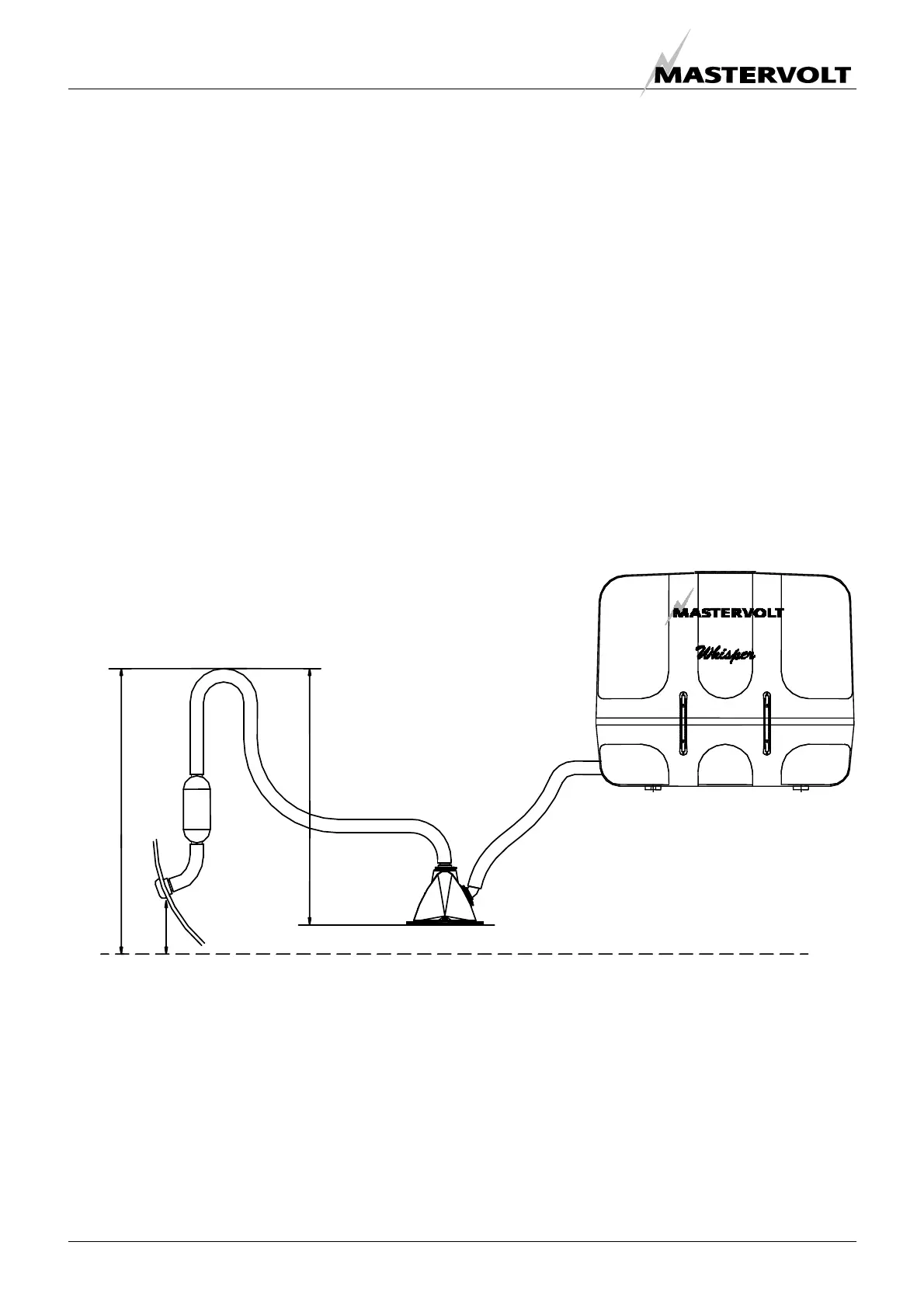
1 STANDARD EXHAUST SYSTEM INSTALLATION
The generating set exhaust system must remain
completely independent and separate from the exhaust
system of any other engine on board. A water lock
prevents the generating set from being flooded by cooling
water and should be installed as close to the generating
set as possible. The lock must be large enough to hold the
entire water volume held in the hose from the top of the
goose neck to the water lock. The water lock must be
installed at the lowest point of the exhaust system (ref. to
fig. 10-1). The exhaust hose must have an inner diameter
of 1
5
/
8
” (40mm), no less, no more. The exhaust system
must be installed so that the back pressure inside the
exhaust does not exceed 1psi (2 inches mercury, 27
inches – 70 cm watercolumn) and total length from the
genearot to the top of the goose neck or or
water/separator does not exceed 10ft (3m). (Refer to
paragraph 5.4.3 of the users manual).
The exhaust hose descends from the capsule to the water
lock. Then the hose rises via the "goose neck" to the
through-hull exhaust outlet, situated minimum 2" (5 cm)
above the water line (ref. to fig. 10-5.) The "goose neck"
must be vertical and situated preferable along the ship’s
keel center line. If the generating set is mounted less than
24" (60 cm) above the waterline, a "goose neck" must be
installed to prevent the engine from overflowing. It is
recommended to install an extra muffler close to the
through-hull fitting.
1 Exhaust water lock; 4 Goose neck;
2 Exhaust outlet muffler; 5 Through-hull exhaust outlet Ø 1
5
/
8
” (40mm);
Fig 10 3 Exhaust line Ø 1
5
/
8
” (40mm) 6 Water level.
Max. length A - B = 10 ft. (3 m)
3
3
4
2
5
6
A
Minimum 60cm (24")
Maximum 150cm (60")
5 cm (2")
B
1

 Loading...