INSTALLATION
4 Copyright © 2009 Mastervolt / July 2009 / WHISPER 6/8/11 / US
3 Never connect the base of the generating set directly
to bulkheads or tanks.
1.4 VENTILATION
The generating set normally draws air from the engine
room. Engine rooms with natural ventilation must have
vent openings of adequate size and location to enable the
generating set to operate without overheating. To allow an
ample supply of air within the temperature limits of the
generating set an opening of at least 16 sq inch (100 cm2)
is required.
A "sealed" engine compartment must have a good
extraction ventilator to maintain reasonable engine room
temperatures. High temperature of intake air reduces
engine performance and increases engine coolant
temperatures. Air temperatures above 104°F (40°C)
reduce the engine power by 1% for each 5°F of rise. To
minimise these effects the engine room temperature must
not be more than 27ºF (15 ºC) above the outside ambient
air temperature.
Apply a combination of ventilators, blowers and air intake
ducting to meet the temperature limit. The air inlet ducts
should run to the bottom of the engine room to clear fumes
from the bilge and to circulate fresh air. Air outlets should
be at the top of the engine room to remove the hottest air.
An engine room blower should be used as an extraction
ventilator to remove air from the engine room.
In cases where it is impossible to meet the above
mentioned temperature limit by using machine room
ventilation, connections are to be made for an air inlet
directly to the enclosure. With these connections the
generating set can be directly connected to an air duct.
Air inlets should be louvered, where appropriate, to protect
the engine room and to protect the generating set from
water spray. As an extra precaution, the fitting of a cowl
ventilator with a cover box located as high as possible, is
recommended.
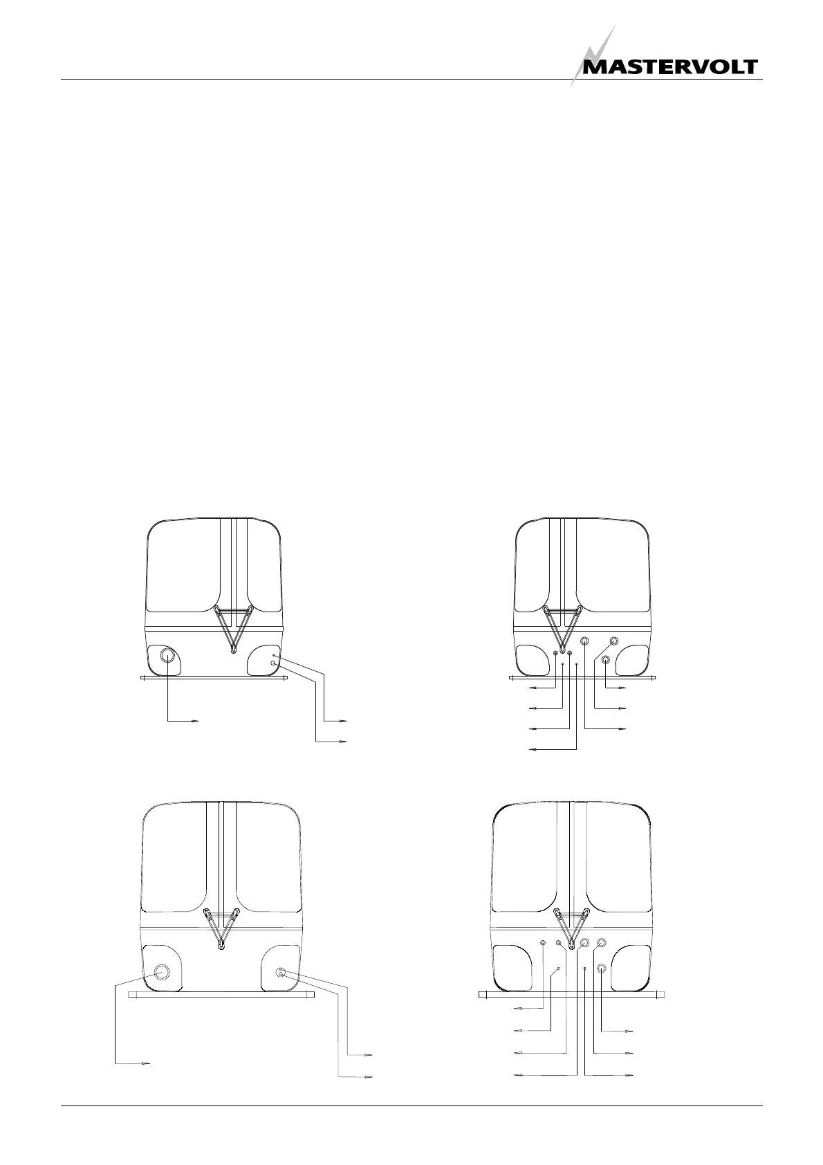
EXHAUST (1)
40 mm
REMOTE CABLE (2)
12x0,3 mm
2
AC CABLE (3)
FUEL RETURN (6)
16 mm
2
BATTERY - (7)
8 mm
FUEL IN (4)
8 mm
16 mm
2
BATTERY + (5)
AIRVENT IN (10)
19 mm
AIRVENT OUT (9)
WATER IN (8)
19 mm
19 mm
EXHAUST (1)
1 5/5” (40 mm)
AC CABLE (3)
REMOTE CABLE (2)
12xAWG22 (0.25mm2)
FUEL IN (4)
5/16” 8mm)
BATTERY + (5)
AWG2 (25mm²)
FUEL RETURN (6)
5/16” 8mm)
BATTERY – (7)
AWG2 (25mm²)
WATER IN (8)
3/4” (19mm)
AIRVENT OUT (9)
3/4” (19mm)
AIRVENT IN (10)
3/4” (19mm)
EXHAUST (1)
1 5/5” (40 mm)
REMOTE CABLE (2)
12xAWG22 (0.25mm2)
AC CABLE (3)
FUEL IN (4)
5/16” 8mm)
BATTERY + (5)
AWG2 (25mm²)
FUEL RETURN (6)
5/16” 8mm)
BATTERY – (7)
AWG2
25mm²
AIRVENT IN (8)
3/4” (19mm)
AIRVENT OUT (9)
3/4” (19mm)
WATER IN (10)
3/4” (19mm)
Figure 2
Whisper 6 and 8
Whisper 11

 Loading...