55
54
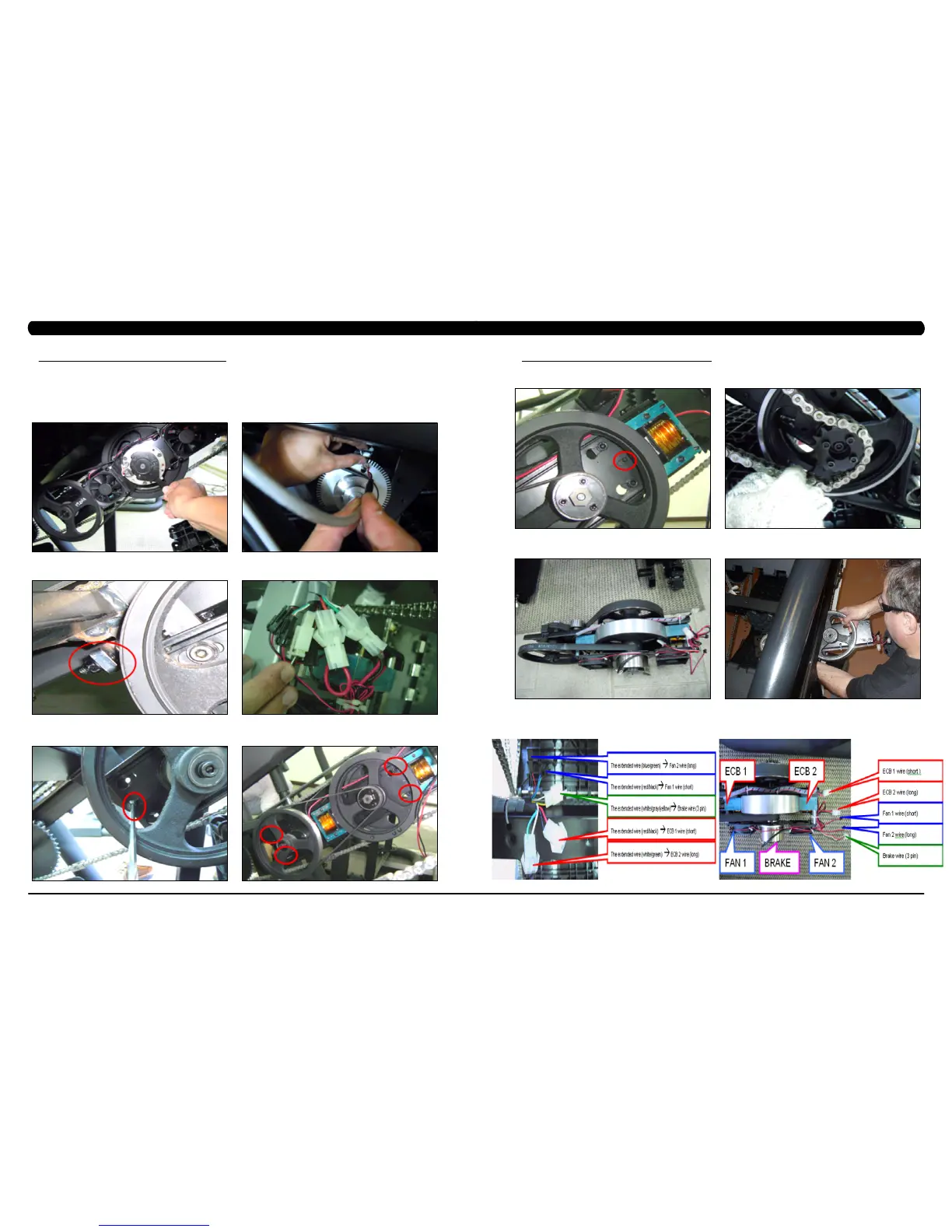
9.10 DRIVE SET REPLACEMENT
*NOTE:Itisrecommendedthat2techniciansbepresentwhenreplacingorremovingthedriveset.Whileitisnotnecessaryto
removethesidecoversorasetofstairs,itmakesitmucheasiertoremovethedrivesetifthesepartsareremovedforaccessibility.
1) Turn off power and disconnect the cord from the machine.
2) Turn the 2 plastic screws counter-clockwise and remove the Matrix logo covers on both sides of the machine.
3) Turn the brake lever to the right to lock the stairs (Figure A) to prevent movement that could cause injury.
4) Disconnect the speed sensor wire (Figure B). NOTE: Use 2 hands to disconnect the speed sensor wire. Do not pull the socket downwards to
disconnect as it will damage the connector.
5) Loosen the screw that applies tension to the chain (Figure C).
6) Disconnect the 5 wire connectors at the top of the drive set (Figure D). These include 2 fan wires, 2 ECB wires, and a brake wire.
7) Loosen the drive set guide screw if tight (Figure E).
8) Remove the 4 screws that hold the drive set to the frame (Figure F).
FIGURE A FIGURE B
FIGURE DFIGURE C
CHAPTER 9: PART REPLACEMENT GUIDE
FIGURE FFIGURE E
9.10 DRIVE SET REPLACEMENT - CONTINUED
9) While a tech is pushing the drive set towards the front of the unit (the drive set will still be supported by the guide screw - Figure G), the other
tech should remove the chain from the sprocket simultaneously (Figure H).
10) Remove the drive set from the unit (Figure I). NOTE: The drive axle will need to be rotated so that the pulleys are horizontal to t through
the side covers (Figure J).
11) Reverse Steps 1-10 to install a new drive set. NOTE: Make sure that the wiring disconnected in Step 5 gets connected correctly. Refer to
Figures K & L. NOTE: Torque the bolts removed in Step 7 to 40N-m.
12) Test the Climb Mill for function as outlined in Section 9.21.
FIGURE HFIGURE G
CHAPTER 9: PART REPLACEMENT GUIDE
FIGURE I
FIGURE LFIGURE K
FIGURE J