Last update: February 2018
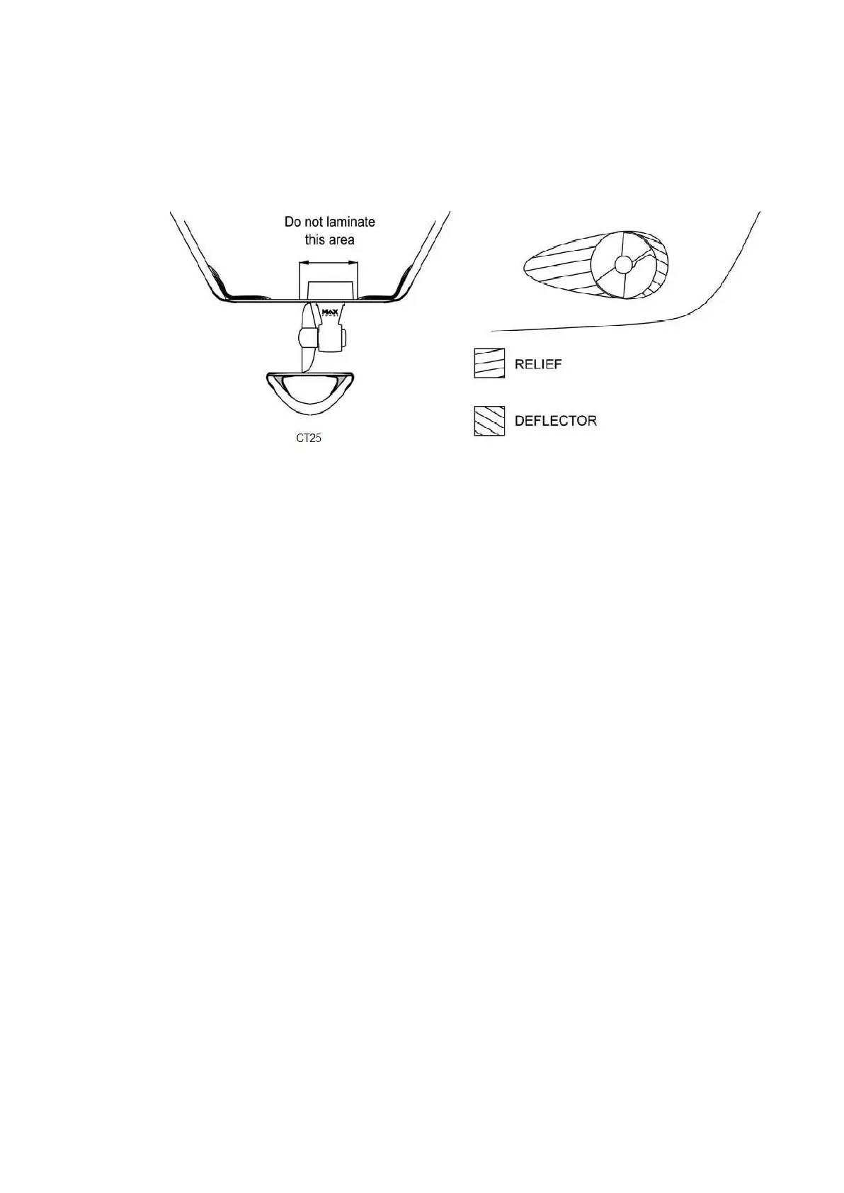
DO NOT LAMINATE THE AREA OF THE TUNNEL TO WHICH THE ELECTRICAL MOTOR
SUPPORT WILL BE FIXED.
3. COMPOSITE MOTOR SUPPORT AND DRIVE LEG
The propeller must be at the center of the tunnel. The motor support and the drive leg will
therefore not be centered in the tunnel.
Locate and mark the intended position of the holes for the fixing screws and the leg hub.
You can use motor’s support and leg’s gasket to mark these holes.
In some cases it will be easier to mark and drill these holes BEFORE laminating the
tunnel.
After drilling, use the gasket to verify the holes’ axes and adjust them with a round file
where necessary.
These holes must be completely clean before inserting the screws.
Position the leg, the gasket (between the leg and the tunnel) and the motor support,
and then tighten the two screws alternatively. Finally, mount the propeller to control the
general alignment.
If the general set-up is correct, remove the propeller, the leg and the gasket.