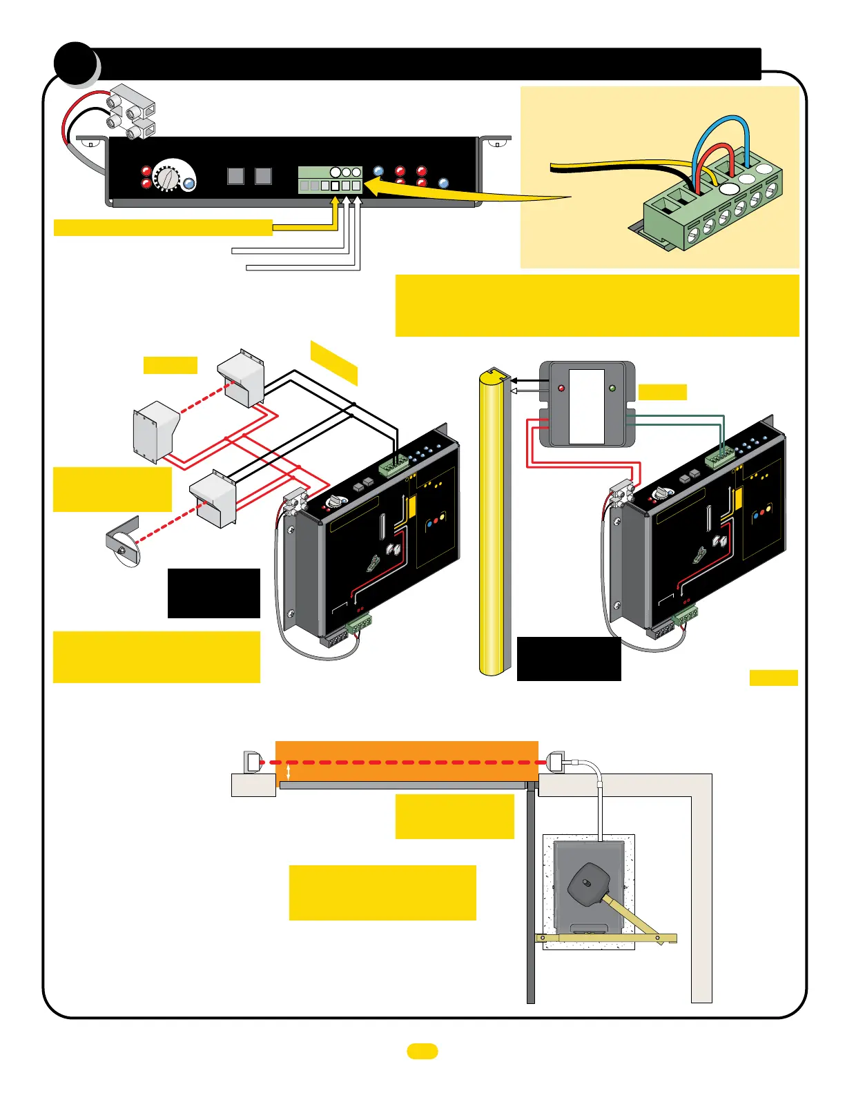
entrapment protection wiring
8
PhotoCell
Edge
UL Entrap
1
2
Limit SW
ON-LINE
MATRIX
JOG
LEFT
JOG
RIGHT
Jog LT
Jog RT
GND
Edge 1
Edge 2
Photo
Cell
ERD
Motor
OverLoad
POWER
MC-200
Motor Controller
16
15
14
13
12
3
4
5
MAX
LED ON
Edge
Sensitivity
ERD
1
2
3
Normally Closed (N.C.)
Jumper UNUSED Entrapment Protection Inputs
or a fault will occur.
Example: Inputs 2 & 3
are NOT used and
MUST be jumpered
to GND.
GND
1
2
3
Typical Wiring For:
Normally Closed (N.C.)
Photo Cell to EDGE 1
Sensor Wire
EDGE 1: MONITORED CLOSE ONLY
Edge 2: LEARNED MONITORED OPEN/CLOSE
Photo Cell: LEARNED MONITORED OPEN/CLOSE
IMPORTANT Sensing devices MUST
be powered by MC-200 or they will
NOT be MONITORED.
IMPORTANT: Photocells
MUST be in alignment
or fault will occur.
IMPORTANT: Photocells
MUST be in alignment
or fault will occur.
NOTE: See manual for more information about learned monitored inputs.
See pages 18-20
for specific
photocell wiring.
PWR 12V
Typical
HARDWiring
For:
Normally Closed (N.C.) Sensing Edge to EDGE 1
GND (C)
EDGE 1 (N.C.)
CLOSING Direction ONLY
Sensing Edge
NOTE: See
manual for more
information
about sensing
edges.
NOTE: Power extension
terminal is connected to 12V
power on back of MC-200.
ONE Entrapment protection sensor MUST installed or operator will NOT
function. It MUST be MONITORED and NORMALLY CLOSED (N.C.).
UL 325 2016 Standard
GND (C)
EDGE 1
(N.C.)
CLOSING Direction ONLY
Reflective
Beam
R
e
flector
PWR 12V
P
olar
ity does NOT matter
12V
Power
Ex
tension
Terminal
12V
Power
Ex
tension
Terminal
GEM-104 MUST be used
Polarity does NOT matter
12 Volt Power Extension Terminal:
Entrapment protection sensor power (12V) MUST be wired to this terminal
or it will NOT be MONITORED by the gate operator.
Pho
to
Ce
l
l
Ed
ge
UL
En
trap
1
2
Limit
SW
ON
-
LIN
E
MA
TR
IX
JOG
LEFT
JOG
R
IG
HT
J
og
LT
Jo
g
R
T
GN
D
Ed
ge
1
Ed
ge
2
Pho
to
Cell
ER
D
Moto
r
O
verL
oad
PO
W
ER
M
C-200
M
ot
o
r
Co
ntro
ller
16
15
14
1
3
12
3
4
5
M
A
X
L
E
D
O
N
Ed
ge
Se
nsiti
vi
t
y
ERD
MOTORPo
w
er In
A
L
A
R
M
B
AT
TE
R
Y
PA
C
K
L
I
M
I
T
S
W
ITC
H
M
OT
OR
IN
P
U
TS
PWR 12V
-
GND
-
-
-
PWR 24V -
GND -
RS-485 (-) -
RS-485 (+) -
MATRIX
1
Edge 1
Moni
t
ored
Reve
r
si
n
g
Ed
g
e
Monitor
ed
Photo
Cell
OR
GND
Jog RT
Jog LT
Entrapment Protect
i
on
Inputs:
M
US
T
ju
mp
er
u
n
u
se
d in
p
ut
s
Entr
a
pm
e
nt Prot
ecti
on
Se
nsor Guidel
ines
1
-
-
-
C
AUTIO
N
:
S
e
e
i
nsta
l
la
ti
o
n
i
n
s
tr
ucti
o
ns.
A
TT
E
NTI
O
N:
Vo
i
r
l
a
n
o
tice
d’
i
n
sta
llati
on
.
Edge 2
Photo Cell
M
C
-
2
00
P
W
R 12
V
MUS
T
b
e
u
s
ed
O
N
LY
p
ow
e
r
e
n
t
r
a
p
m
en
t
pr
o
t
ect
io
n
s
e
n
s
o
r
s
wit
h
M
C-
2
00
P
W
R
1
2V
Inputs
&
MUS
T be “LE
A
R
N
E
D
”
t
o
MO
N
ITOR
se
nsors.
T
o
LEA
R
N
input
s
&
:
1.
MON
I
TOR
ED
Sensor
s
MU
ST
be
w
ired
t
o
inputs B
EF
ORE
t
hey
c
an
be
l
earned.
An
y
unus
ed
input
s
MU
ST
be
jumpered.
2.
R
ev
er
s
ing Edge
and/or Phot
o C
ell
can
be
w
ir
ed
to
ei
t
her
input
2
or
3.
3.
Press
and
H
OL
D
the OPEN
&
S
T
OP
but
t
ons
at
t
he
s
ame
t
im
e
on Matr
i
x 1
unt
il
beep
is
heard,
le
arn
mode
be
gins
.
Learn
mode la
s
t
s
f
or
5 m
in.
indi
cated
by
beeping.
4.
LE
D
s
WIL
L
be ON
f
or eac
h
det
ec
t
ed
s
ensor
on
M
C
-200.
LE
D
s
WIL
L
be
ON
f
or
B
OTH
M
C
-200s
w
hen
dual
operat
or
s are
used.
5.
Pr
es
s
ST
OP but
t
on
again w
it
hin
5
m
in
.
t
o learn
s
ens
or
s
and
end
learn
m
ode,
beeping
s
t
ops.
I
nput
s
are
now
MON
I
TOR
ED
.
2
3
2
3
2
3
•
A sensor
MUST
be wir
ed
t
o
E
DG
E
1
or
op
er
ator
WI
L
L
NOT
fu
n
c
ti
on.
•
Wi
r
e
NO
RMALLY
CLO
S
E
D
(
N.C.)
MO
NIT
O
RED
sensor
s
O
NL
Y
, to
ea
c
h
op
er
ator
’s
MC-
20
0
wh
e
n du
al
op
e
r
a
to
r
s
a
r
e
u
s
e
d.
•
Rev
er
s
i
ng
E
dg
e an
d/
or
P
hoto
Ce
l
l
can
be
wi
r
ed
to
ANY
of th
e
3 Inpu
ts
.
•
MC-
200
P
WR
12V
MUST
b
e us
ed
to
p
o
w
er
MO
NI
T
ORE
D
s
e
nsors.
•
U
N
U
S
ED
in
pu
ts
MUS
T
r
ema
in
J
U
M
P
E
R
ED
or
fa
u
lt wi
l
l
oc
cur.
GN
D
1
2
3
OP
E
N
ST
O
P
CLOSE
M
OT
O
R
M
OT
I
O
N
MC-200 Swing
Edge 1
CLOSE ONLY
ON = Obstruction
BLINKING = Fault
PWR
MON.
SAFETY
INPUT
GEM - 104
10K Edge
Normally
Closed
Pho
to
Ce
l
l
Ed
ge
UL
En
trap
1
2
Limit
SW
ON
-
LIN
E
MA
TR
IX
JOG
LEFT
JOG
R
IG
HT
J
og
LT
Jo
g
R
T
GN
D
Ed
ge
1
Ed
ge
2
Pho
to
Cell
ER
D
Moto
r
O
verLoa
d
PO
W
ER
M
C-
200
M
ot
o
r
Co
ntro
ller
16
15
14
1
3
12
3
4
5
M
A
X
L
E
D
O
N
Ed
ge
Se
nsiti
vi
t
y
ERD
MOTOR
Po
w
er In
A
L
A
R
M
B
AT
TE
R
Y
PA
C
K
L
I
M
I
T
S
W
ITC
H
MOT
OR
IN
P
U
TS
PWR 12V
-
GND
-
-
-
PWR 24V -
GND -
RS-485 (-) -
RS-485 (+) -
MATRI
X
1
Edge 1
Moni
t
ored
Reve
r
si
n
g
Ed
g
e
M
onitored
Photo
Cell
OR
GND
Jog RT
Jog LT
Entrapment Protect
i
on
Inputs:
MUS
T
ju
mper
u
n
us
e
d in
p
ut
s
Entr
a
pm
ent Prot
ecti
on
Se
nsor Guidel
in
e
s
1
-
-
-
C
AUTIO
N
:
S
ee
i
nsta
l
la
ti
o
n
i
n
s
tr
ucti
o
ns.
A
TT
E
NTI
O
N:
Vo
i
r
l
a
n
oti
ce
d’
i
nsta
llation.
Edge 2
Photo Cell
M
C
-2
00
P
W
R 12V
MUS
T
b
e
u
s
ed
O
N
LY
p
ow
e
r
e
n
tra
p
m
en
t
pr
o
t
ec
t
io
n
s
e
n
s
o
rs
wit
h
M
C-
2
00
P
W
R
12V
Inputs
&
MUS
T be “LE
A
R
N
E
D
”
to
MO
N
ITOR
se
nsors.
To LEA
R
N
input
s
&
:
1.
MON
I
TOR
ED
Sensor
s
MU
ST
be
w
ired
t
o
inputs
B
EF
ORE
t
hey
c
an
be
l
earned.
An
y
unus
ed
input
s
MU
ST
be
ju
mpered.
2.
R
ev
er
s
ing Edge and/or
Phot
o C
ell
c
an
be
w
ir
ed
to
ei
t
her
input
2
or
3.
3.
Pr
ess
and
H
OL
D
the OPEN
&
S
T
OP
but
t
ons
at
t
he s
ame
t
im
e
on
Matr
i
x 1
unt
il
beep is
heard,
le
arn
mode
be
gins.
Learn
mode la
s
t
s
f
or
5 min
.
indi
c
ated
by
beeping.
4.
LE
D
s
WIL
L
be ON
f
or
eac
h
det
ec
t
ed
s
ens
or
on
M
C
-200.
LE
D
s
WIL
L
be
ON
f
or
B
OTH
MC
-200s
w
hen
dual
operat
or
s are
used.
5.
Pr
es
s
ST
OP
but
t
on
again w
it
hin
5
m
in
.
t
o learn
s
ens
or
s
and
end
learn
mode,
beeping
s
t
ops.
I
nput
s
are
now
MON
ITOR
ED.
2
3
2
3
2
3
•
A s
ens
or
MUST
be
wi
r
ed
t
o
E
DG
E
1
or
oper
at
or
WI
L
L NOT fu
n
c
ti
on.
•
Wi
r
e
NO
RMAL
LY
CLO
S
E
D
(
N.C.)
MONIT
O
RED
sensor
s
O
NL
Y
, to
ea
c
h
oper
ator
’s
MC-
20
0
wh
e
n du
al
oper
a
to
r
s
ar
e
u
s
e
d.
•
Rev
er
s
i
ng
E
dg
e and
/o
r
P
hot
o
Ce
l
l
can
be wi
r
ed
to
ANY
of th
e
3 Inpu
ts
.
•
MC-
200
P
WR
12V
MUST be
us
ed to
p
o
w
er
MO
NI
TORE
D
s
e
nsors.
•
U
N
U
S
ED
in
put
s
MUS
T
r
em
ain
J
U
M
P
E
R
ED
or
fa
u
lt wi
l
l
oc
cur.
GN
D
1
2
3
OP
E
NS
TO
P
CL
OSE
M
OT
O
R
M
O
T
I
O
N
MC-200 Swing
Edge 1
CLOSE ONLY
RecrTrans
Thru-Beam
Entrapment Protection Device Locations:
CLOSING Direction
Photocell ONLY
Continued on next page.
Entrapment Area
Gate Open
Gate Closed
Dual Gate Operators NOTE: Connect CLOSING Direction
photocell to the PRIMARY gate operator’s MC-200.
Run conduit
to operator
CLOSING direction photocell
to MC-200 EDGE 1 input.
Beam: 5” or LESS
from CLOSED gate.
IMPORTANT: Entrapment
Protection Photocells MUST be
Monitored Normally Closed Type.
See page 21 to wire
a Gate Link wireless
transmitter.
7
UL 325 2016 Standard-Megatron Quick Install Rev 10
 Loading...