21
Over voltage protection for PN
PL
Flash 21 times
DC bus-bar high voltage protection
PH
Flash 11 times
PFC protection
HC
Flash 6 times
The four-way valve is abnormal
U7
Flash 20 times
"88" Display state under test state: minimum cooling(heating)-P0; middle cooling(heating)-P3 Nominal cooling(heating)-P1;
maximum cooling(heating)–P2; Corresponding indicator lamp will be on for 0.3s and off for 0.3s
8.2. How to Check simply the main part
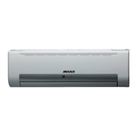
8.2.1 U8 Malfunction
Possible causes:
1. The controller diagnoses incorrectly due .to instant energization after de-energized while the capacitor discharges slowly;
2. Malfunction of the zero-cross detection circuit of the mainboard.
See the flow chart below:
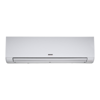
8.2.2. C5 Malfunction
Possible causes:
1. There is no jumper cap on the controller;
2. Jumper cap is not inserted properly and tightly;
3. Jumper cap is damaged;
4. Controller is damaged.
See the flow chart below:
“U8” is displayed on the unit.
Re-energize 1 minute after de-erergization
Is “U8” still displayed?
The zero-cross detection circuit of the mainboard
is defined abnormal. Replace the mainboard.
Malfunction is eliminated.
The unit returns to normal.
Conclusion: U8 is displayed due to
instant energization after de-energization
while the capacitor discharges slowly.
No
C5 is displayed on the unit.
Is there jumper cap on the controller? Install a matching jumper cap.
Is there jumper cap inserted incorrectly or improperly?
Is the malfunction eliminated?
Replace the jumper cap
Is the malfunction eliminated?
The mainboard is defined abnormal; replace it
End
Re-insert the jumper cap.
Is the malfunction eliminated?
Yes
Yes
Yes
Yes
Yes
No
No
No
No
No