Do you have a question about the MAXA GRIMPER FAN Series and is the answer not in the manual?
Details intended use, limitations, and general safety rules for the unit.
Information on the unit's dataplate, frame, filters, insulation, coil, and connections.
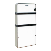
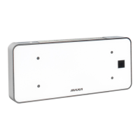
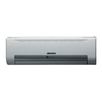
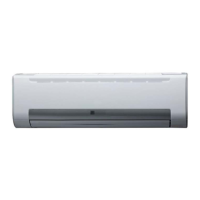
Detailed identification of both external and internal components with diagrams.
Details airflow, total and sensible cooling capacity for 2-pipe systems.
Details water flow rate and pressure drop for 2-pipe systems.
Details airflow and thermal capacity for 2-pipe systems.
Details water flow rate and pressure drop for 2-pipe systems.
Details airflow, total and sensible cooling capacity for 4-pipe systems.
Details water flow rate and pressure drop for 4-pipe systems.
Details airflow and thermal capacity for 4-pipe systems.
Details water flow rate and pressure drop for 4-pipe systems.
Details on main coil, motor input power, and towel warmer function absorption.
Provides sound power and pressure levels in dB(A) for various settings.
Diagrams showing unit dimensions, clearances, and weight.
Guidelines for handling, skilled installation, regulations, and general safety.
Covers spare parts, environmental laws, potential risks, and condensation notes.
Instructions for structural support, antivibration, minimum clearances, and condensate drainage.
Steps for removing towel bar handles, screws, and the glass panel.
Procedure for removing outlet grille, filter, and metal side flanks.
Steps to remove front panel, flank screws, metal panel, and PCB cover for access.
Instructions for preparing holes, fixing tie rods, and tilting for condensate drainage.
Details on thread size, pressure, shut-off valves, and condensate drainage checks.
Specifications for the condensate drain outlet, pipe gradient, and siphon.
Covers power supply checks, safety measures, and sealing holes after wiring.
Explains remote control, thermostat options, and provides wiring diagrams.
Table detailing the DIP switch settings for various fan speed (RPM) configurations.
Instructions for cleaning the coil and filter, and safety for electrical disconnection.
Lists common issues like motor not turning or reduced performance and their solutions.
Detailed steps for installing the water probe sensor on the coil.
Shows pipe components, connection without insulation, and insulation requirements.
Wiring diagram for the 230V-50Hz actuator with micro version.
Provides overall dimensions, minimum clearances to ceiling/floor, and connection points.
| Brand | MAXA |
|---|---|
| Model | GRIMPER FAN Series |
| Category | Air Conditioner |
| Language | English |