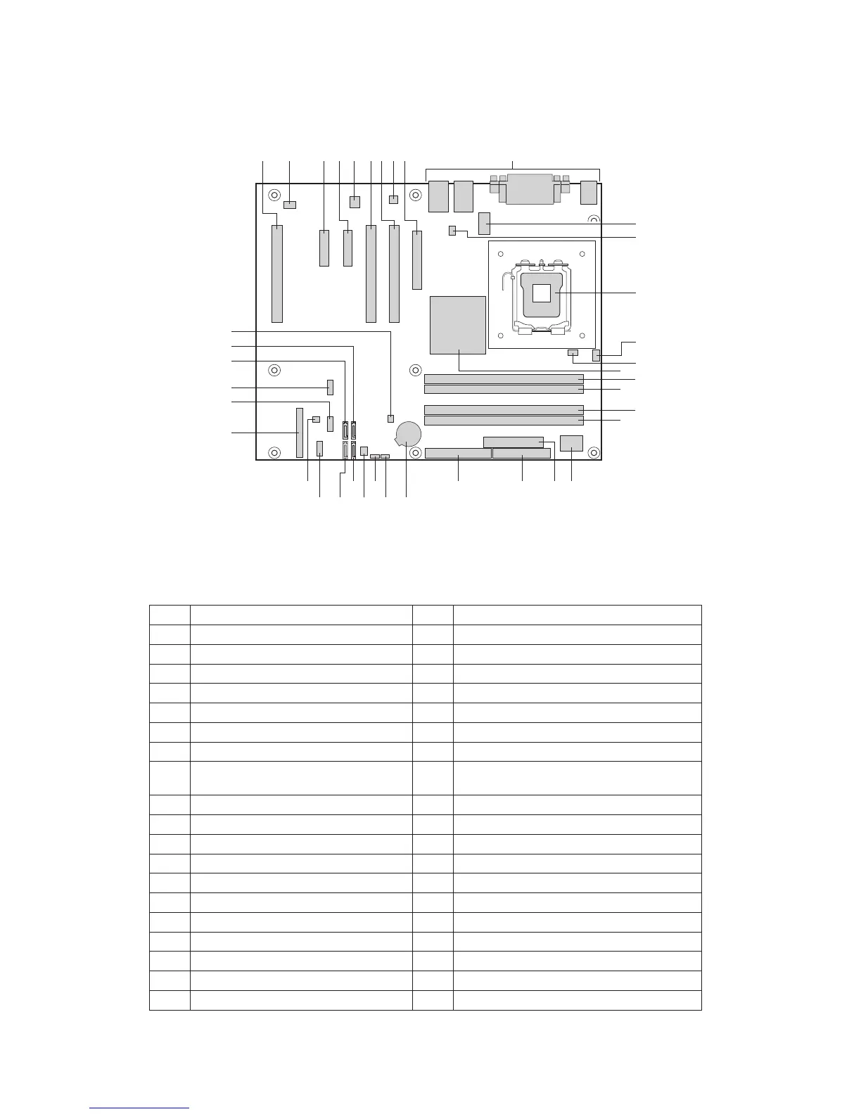
Board Components
Figure 3 shows the approximate location of the major components on board.
Table 2. Board Components
Label Description Label Description
A. Conventional PCI Slot 3 T Channel B DIMM 0 Socket (black)
B. Rear Fan Connector U.
I/O Controller
C. PCIE Slot 2 (x4 Connector, x1 Bus) V. 2 × 12 Power Connector
D. PCIE Slot 1 (x4 Connector, x1 Bus) W. Diskette Drive Connector
E. Intel
®
82551QM LAN Controller X. Parallel ATA IDE Connector
F. Conventional PCI Slot 2 Y. Battery
G. Conventional PCI Slot 1 Z. Bios Configuration Jumper
H. Marvell* Yukon* 88E050 PCI Express*
Gigabit Ethernet Controller
AA. Clear CMOS Jumper
I. PCI Express* 1x8 Slot BB. Front Fan Connector
J. Back Panel I/O
CC. SATA 3 Connector
K. 2 × 4 Power Connector DD. SATA 2 Connector
L. Chassis Fan Connector EE. Serial B Connector
M LGA775 Processor Socket FF. SCSI LED Connector
N CPU Fan Connector (4 Pins) GG. Front Panel Connector
O Hardware Management Controller HH. Front Panel USB 2
P Intel
®
E7221MC GMCH II. Front Panel USB 1
Q Channel A DIMM 0 Socket (blue) JJ. SATA 0 Connector
R Channel A DIMM 1 Socket (black) KK. SATA 1 Connector
S Channel B DIMM 0 Socket (blue) LL. Chassis Intrusion Connector
Figure 3. Board Components