16
model no. 054-6810-8 | contact us 1-888-670-6682
SETTING THE CUTTING DEPTH FOR
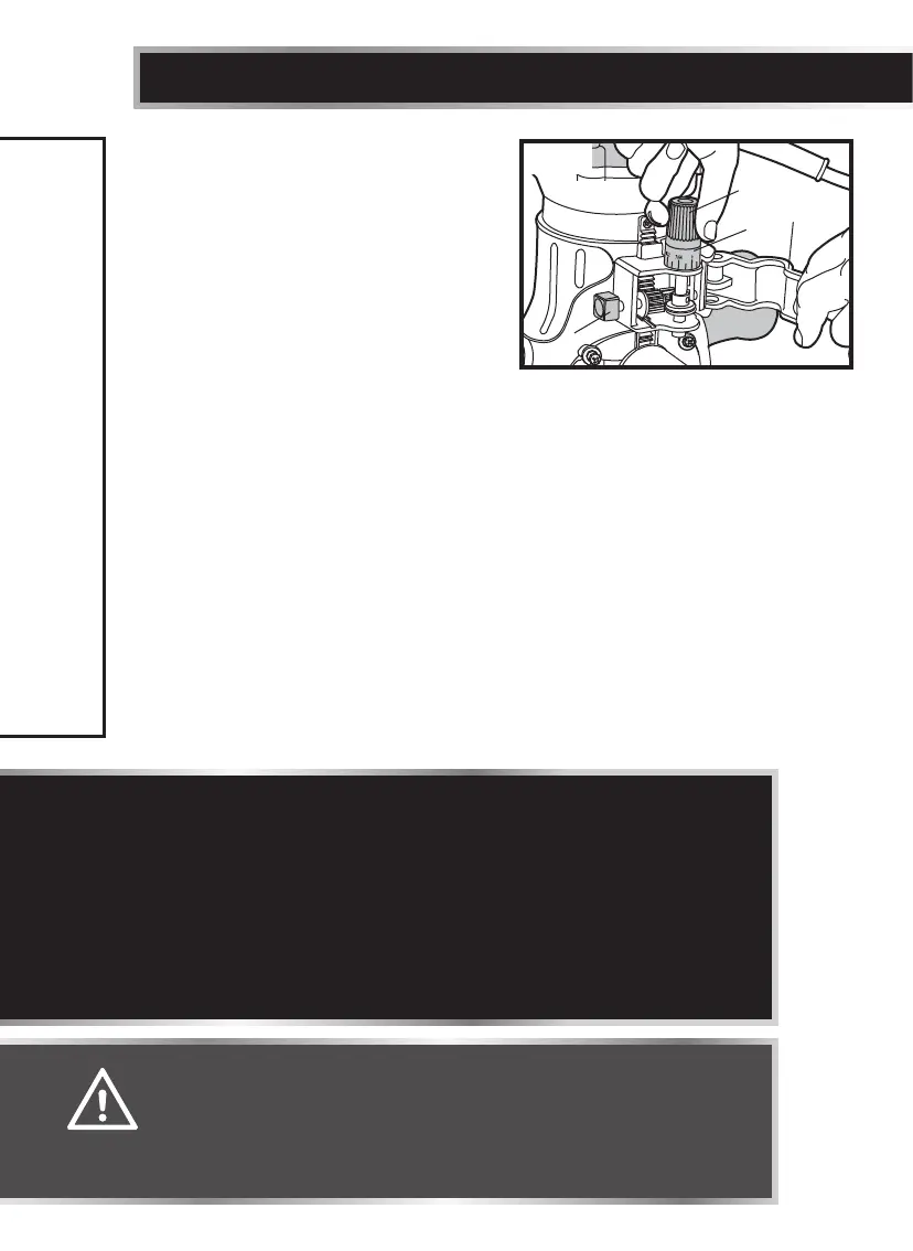
FIXED BASE ROUTING (see g 9)
The fixed base is designed with a
micro-fine adjustment worm-gear
system. When the bit is lowered to the
approximate desired position (rough
setting), the system can then be
micro-adjusted to the precise depth.
Rough Adjustment:
Depressing the Rough-adjustment Knob (B) allows the operator to quickly lower
or raise the cutter bit to an approximate depth setting.
Micro-fine Adjustments:
The Depth-indicator Ring (D) is located on the Micro-fine Adjustment Dial, and
is marked in 1/64" increments. Turning the Micro-fine Adjustment Dial clockwise
180° (1/2 turn), lowers the cutter bit 1/16". One full turn clockwise (360°) - zero
“0” to zero “0” - lowers the bit 1/8".
The system allows a maximum of 7 full 360° clockwise revolutions in order to
lower the cutter bit 7/8" (22.3 mm). The Depth-indicator Ring may be reset to
zero “0” without moving the Micro-fine Adjustment Dial. This allows the user to
begin adjustments from any desired reference point.
ASSEMBLY INSTRUCTIONS
WARNING!
• Ensure that the router is never turned on or connected to the
power source when assembling parts, making adjustments, or
installing or removing collets and cutter bits, during cleaning,
or when it is not in use. Disconnecting the router will prevent
accidental start-ups, which could cause serious personal injury.
NOTICE:
• All depth adjustments on the fixed base must be made with the motor
clamp loosened.
• For all fixed-base routers, the cutter bit depth equals the amount of the
cutter that is exposed below the surface of the sub-base.
• Be sure the worm-gear system is engaged before making fine adjustments.
Test it by turning the Micro-fine Adjustment Dial (C) clockwise and counter-
clockwise to see if the bit lowers and rises. If it does not, press the Rough-
adjustment Knob, and turn the Micro-fine Adjustment Dial until the gears
engage, and then reset zero “0” on Depth-indicator Ring (D).
A
D
B
C
g 9