14
model no. 054-6810-8 | contact us 1-888-670-6682
ASSEMBLY INSTRUCTIONS
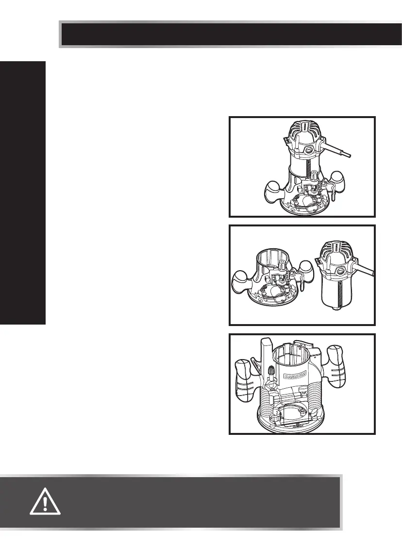
SWITCHING FROM THE FIXED BASE TO THE PLUNGE BASE
(see g 4 to g 7)
To remove the fixed base
1. Unplug the router.
2. Loosen the lock lever on the fixed
base.
3. Hold the motor pack with one hand,
and depress and hold the adjustment
button with the other hand.
4. Remove the motor pack from the fixed
base.
To Install the plunge base
1. Unplug the router.
2. Loosen the lock lever
3. Tighten the locking arm for stability.
4. Align the tab on the motor pack with
the slot in the plunge base.
5. Tighten the lock lever.
6. Loosen the locking arm.
To install the chip shield on the plunge
base
The chip shield on the plunge base is held
in position with a screw. To remove the
chip shield from the plunge base, unplug
the router and simply loosen the screw
and take the chip shield off of the base
(fig 3).
ASSEMBLY INSTRUCTIONS
WARNING!
• Always unplug the tool from the power source before making any
adjustment or attaching accessories.
g 4
g 6
Plunge
base
g 5
Fixed Base
Motor