2726
NOTE: Anti-kickback pawls should only be installed for through cuts.
• Loosen the tri-wing knob (1) to allow approximately
1/8" (3.2 mm) gap between riving knife (2) and lock
plate (3).
• Push the lock knob (4) to the riving knife (2) until
the riving knife (2) unlocks from the locking pin.
• Loosen the lock knob (4) and pull riving knife (2) up
or down until the pin is reengaged and the riving
knife is in the middle position.
• Tighten the tri-wing knob (1).
• Reinstall the table insert.
PLACE IN THE LOWEST POSITION (THE UPPER
HOLE IN THE RIVING KINIFE) ONLY FOR SHIPPING
TO INSTALL THE ANTI-KICKBACK PAWLS AND
BLADE GUARD (Fig. 14-18)
• Unplug the saw.
• Set the blade angle to 0°.
• Raise the saw blade to maximum height by turning
height adjustment knob clockwise.
• Place the riving knife in the highest position.
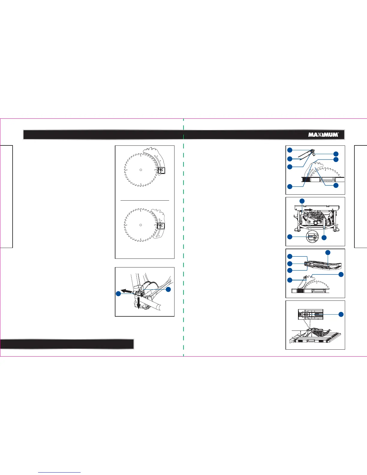
TO INSTALL ANTI-KICKBACK PAWLS: (Fig. 14-15)
• Unplug the saw.
• Pull out and hold knob (1) and push anti-kickback
pawls down, remove it from the anti-backpawls
storage (2) at the bottom left rear side of the saw.
(Fig. 14)
• Pull out and hold knob (1). Place the spring pin (3)
on the anti-kickback pawls (4) into the notch (5)
indicated on the riving knife (6).
• Press anti-kickback pawls assembly completely
down and push spring pin down to secure in
position.
• Release knob (1) to insert the pin (7) into hole (8)
indicated on the riving knife (6).
IN UP POSITION FOR
THROUGH CUTTING
IN MIDDLE POSITION FOR
NON-THROUGH CUTTING
TO INSTALL THE BLADE GUARD: (Fig. 16-17)
• Unplug the saw.
• Hold the knobs (9) (one on either side of the blade
guard) and push the knobs forward to the front of
the blade guard and down until the pin comes out
from the notch in the mounting bracket (blade
guard storage I) (10) at top left rear side of the saw,
then raise the blade guard up from the U-bracket
(blade guard storage II) (11) at bottom right rear
side of the saw and remove the blade guard from
the blade guard storage. (Fig. 16)
• Hold and push knobs (9) forward to the front of the
the blade guard. Place the pin (12) on the blade
guard (13) into the notch (14) indicated on the riving
knife (6).
• Pull blade guard fully back onto riving knife. Push
pin and release it to lock guard into position.
Make sure that blade guard body is parallel to the
table. If it is not, adjust the set screw (15) as
necessary. (Fig. 18)
model no. 055-6766-2 | contact us 1-888-670-6682
ASSEMBLY
model no. 055-6766-2 | contact us 1-888-670-6682
ASSEMBLY
Fig. 13
Fig. 15
3
1
5
6
4
7
8
Fig. 14
1
2
a
b
Fig. 17
12
6
13
14
Fig. 16
a
b
c
10
11
Fig. 18
9
9
9
15
 Loading...