32
model no. 055-6767-0 | contact us 1-888-670-6682
ADJUSTMENTS
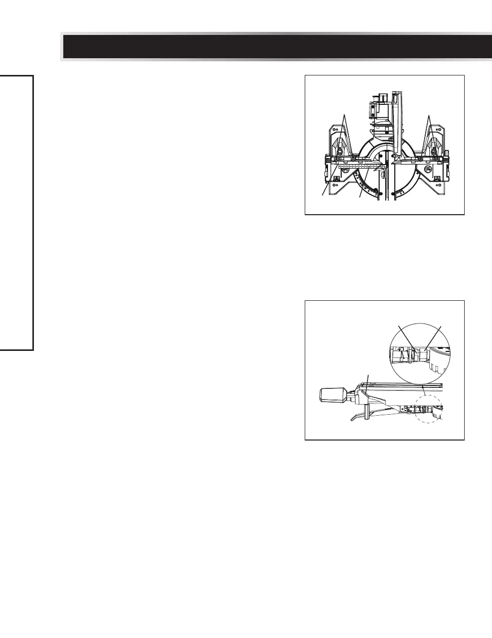
ADJUSTING FENCE SQUARENESS (Fig. 22)
Remove the left side and right side sliding
fences.
• Loosen the four fence locking bolts (1).
• Lower the cutting arm and lock in position.
• Using a square (2), lay the heel of the
square against the blade and the ruler
against the fence (3) as shown.
• Adjust the fence 90° to the blade and
tighten the four fence locking bolts (1).
NOTE: If the saw has not been used
recently, recheck blade squareness to the
fence and readjust if needed.
• After fence has been aligned, replace the
left side and right side sliding fences.
• Using a scrap piece of wood, make a cut at
90° then check squareness on the piece.
Readjust if necessary.
QUICK-CAM MITRE TABLE LOCK
ADJUSTMENT (Fig. 23)
• Press down and lock the quick-cam mitre
table lock (1).
• If the table moves with the quick-cam mitre
table lock in the down position, turn the
stop nut (2) to the left as shown using a
1/2" (13 mm) wrench to extend the locking
arm against the base of the mitre saw.
• Test the quick cam mitre lock to verify it
locks the table into position securely.
• Turn the lock nut (3) to the right as shown
to lock the mitre locking mechanism
into place.
Fig. 22
11
2
3
Fig. 23
1
2
3