48
model no. 055-6767-0 | contact us 1-888-670-6682
OPERATION
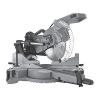
33.9° BEVEL DETENT PIN FOR CROWN
MOULDINGS (Fig. 42)
• Push the bevel detent stop pin (1) in
towards the rear of the machine.
• Loosen the bevel lock handle (2) by
pulling up.
• Rotate the cutting head until the bevel
detent pin stops the bevel angle at 33.9° on
the bevel scale.
• Tighten the bevel lock handle (2) by
pressing down before making your cut.
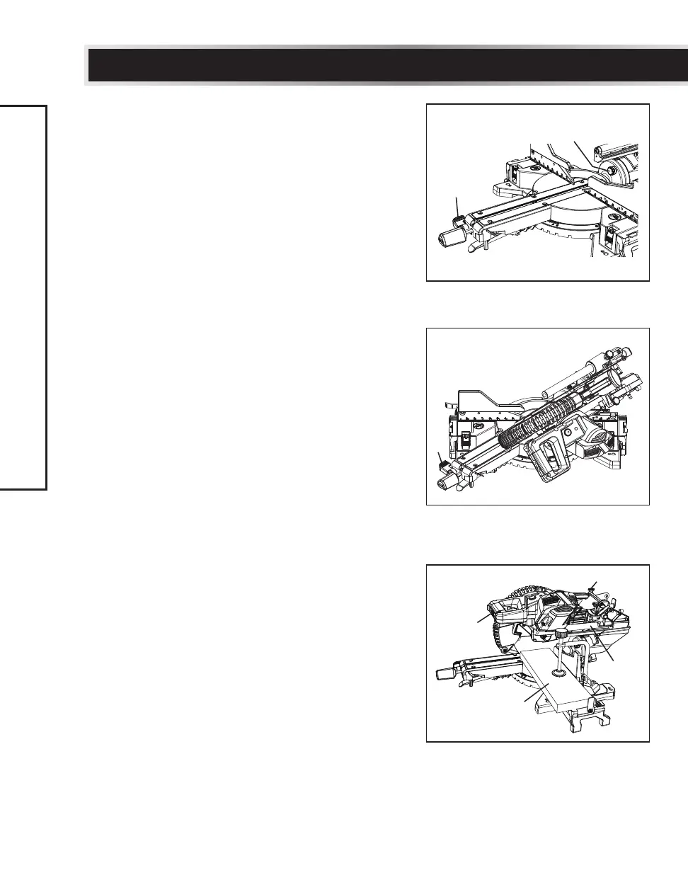
COMPOUND CUT (Fig. 43)
A compound cut is the combination of a mitre
and a bevel cut simultaneously.
• Extend the fence by sliding it out to the
required location or remove the left/right
sliding fence if necessary. See “SLIDING
FENCE” or “REMOVING OR INSTALLING
THE SLIDING FENCE.”
• Set the desired bevel angle using the bevel
locking handle (1).
• Set the desired mitre angle and lock into
position. See “MITRE CUT.”
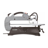
SLIDE CUTTING WIDE BOARDS UP TO
12 1/2" WIDE (Fig. 44)
To slide cut wide boards:
• Unlock the sliding carriage lock knob (1)
and allow the cutting head assembly to
move freely.
• Set both the desired bevel angle and/or the
mitre angle and lock into position.
• Use a hold-down clamp to secure the
workpiece.
• Turn the laser guide on and position the
workpiece on the table for pre-alignment of
your cut.
Fig. 42
1
2
Fig. 43
Fig. 44
1
2
4
3
1