47
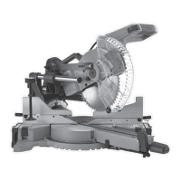
BEVEL CUT (Fig. 40, 41)
• When a bevel cut is required, loosen
the bevel locking handle (1) by turning
it clockwise.
• Tilt the cutting head to the desired angle,
as shown on the bevel scale (2).
• The blade can be positioned at any angle,
from a 90° straight cut (0° on the scale) to
a 45° left bevel. Tighten the bevel locking
handle (1) to lock the cutting head in
position. Positive stops are provided at 0°,
33.9° and 45°.
NOTE: The saw comes with a 33.9° bevel
detent pin for setting up crown moulding
cuts when the angle of the walls equals 90°.
• Turn the laser guide on and position the
workpiece on the table for pre-alignment of
your cut.
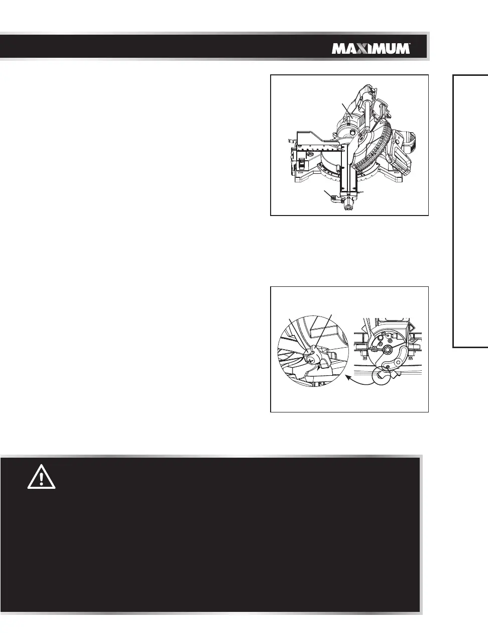
NOTE: If 47
° left bevel is necessary,
slide the
bevel stop plate (3) clockwise away from the
stop block (4) to achieve 47
° left bevel.
WARNING!
• The sliding fence must be extended to the left when making left bevel
cuts. The sliding fences note three bevel angles where the user must
adjust the fences to match the degree of the bevel cut. Failure to extend
the sliding fence will not allow enough space for the blade to pass
through which could result in serious injury. At extreme mitre or bevel
angles the saw blade may also contact the fence.
• The left sliding fence must be removed when making left bevel angle
cuts greater than 33.9° in combination with any right or left mitre angle.
This fence must also be removed whenever a 45° bevel angle is desired
with a mitre angle greater than 31.6°.
• The right sliding fence must be removed when making any right bevel
angle cuts.
Fig. 40
OPERATION
Fig. 41
3
4
1
2