52
model no. 055-6767-0 | contact us 1-888-670-6682
OPERATION
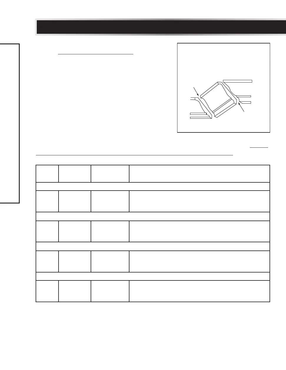
KEY
BEVEL
SETTING
MITRE
SETTING
TYPE OF CUT
Inside corner - Left side
IL 33.9° 31.6° Right
1. Position top of moulding against fence.
2. Mitre table set at RIGHT 31.6°.
3. LEFT side is finished piece.
Inside corner - Right side
IR 33.9° 31.6° Left
1. Position bottom of moulding against fence.
2. Mitre table set at LEFT 31.6°.
3. LEFT side is finished piece.
Outside corner - Left side
OL 33.9° 31.6° Left
1. Position bottom of moulding against fence.
2. Mitre table set at LEFT 31.6°.
3. RIGHT side is finished piece.
Outside corner - Right side
OR 33.9° 31.6° Right
1. Position top of moulding against fence.
2. Mitre table set at RIGHT 31.6°.
3. RIGHT side is finished piece.
NOTE: The chart below references a compound cut for crown moulding ONLY
WHEN THE ANGLE BETWEEN THE WALLS EQUALS EXACTLY 90°.
• In order to accurately cut crown moulding
for a 90° inside or outside corner, lay the
moulding with its broad back surface flat
on the saw table.
• When setting the bevel and mitre angles
for compound mitres, remember that the
settings are interdependent; changing one
changes the other, as well.
Fig. 50
Compound cut crown mouldings
Inside corner
Outside corner
OR
OL
IR
IL
Bevel/Mitre Settings
Settings for standard crown
moulding lying flat on compound
mitre saw table