ENGLISH
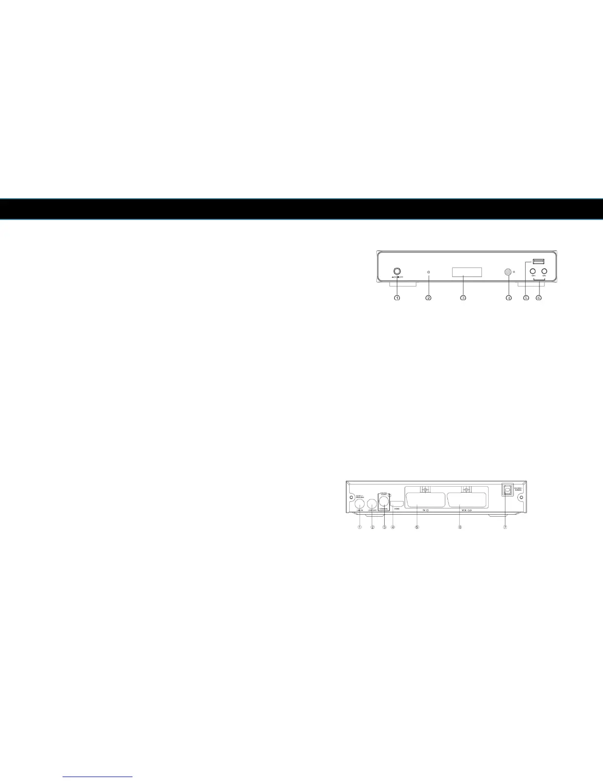
2.3 Front Panel
1 POWER SWITCH: Used to switch the receiver on or off.
2 STANDBY INDICATOR: Used to visually show the power state of the receiver, the LED
will turn red if the receiver enters standby mode.
3 LED DISPLAY: Used to display time or channel number.
4 REMOTE CONTROL SENSOR: Used to receive the signal from the remote control.
5 USB: Data input from USB media
6 CHANNEL UP/DOWN: Used to change channels.
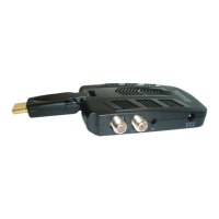
2.4 Back
1 LNB IN: Used to connect the LNB to receive the signal.
2 LOOP OUT: This socket will bypass the Satellite signal to another receiver.
3 COAXIAL: Digital Audio SPDIF output.
4 HDMI OUT: Digital Audio/Video output for TV/DVD etc.
5 TV SCART: Analogue Video output for TV.
6 VCR SCART: Analogue Video output for VCR/DVD.
7 MAINS CABLE: This is used to connect to your main power
supply.
8