Page 6 of 10 M-KIT100/101/102 Assembly Instrucons 181-03001
These instrucons must be followed exactly. Failure to follow these instrucons could damage the product or result in injury to persons using or
assembling the product. Maxon Furniture Inc. shall not be liable for any costs, loss, damage, expenses or injuries resulng from failure to properly
assemble the product in accordance with these instrucons.
Maxon Furniture Inc. Customer Service: 1-800-876-4274
While holding the Angle Alignment Bracket in 9.
place, connect the second Panel by inserng
the I-Beam Panel Connectors as directed in
Steps 5-6.
Add one PLNR4236 Panel to the L-shape by 10.
inserng one Straight Alignment Bracket
between the adjoining PLNR4236 Panels and
connecng with the I-Beam Panel Connectors
(Figure 5).
Trim the excess I-Beam Panel Connector 11.
length with wire cuers or snips as directed
in Step 6.
TIP! Leveling the panels by adjusng
the Glides may ease the I-Beam Panel
Connector installaon.
To secure the PLNR4236 Panels, center the 12.
Lock Bar over two PLNR4236 Panels (Figure
5) and aach with two #8 x 1/2” Flat Head
Self Drilling Screws (Figure 6).
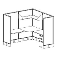
Repeat Steps 3 - 6 to aach the remaining 13.
PLNRCP42 Corner Post to the assembled
PLNR4236 Panels (Figure 7).
Repeat Steps 7 - 9 to aach the remaining 14.
PLNR4236 Panel. This completes the
installaon of the PLNR4236 Panels.
Figure 7
Figure 6
Figure 5
Straight Alignment
Bracket
Panel Connectors
Lock Bar
#8 x 1/2" Phillips
Flat Head Screw
TOP VIEW
#8 x 1/2" Phillips
Flat Head
Lock Bar centered
over panels.
Corner
Post
PLNR4236
Panel