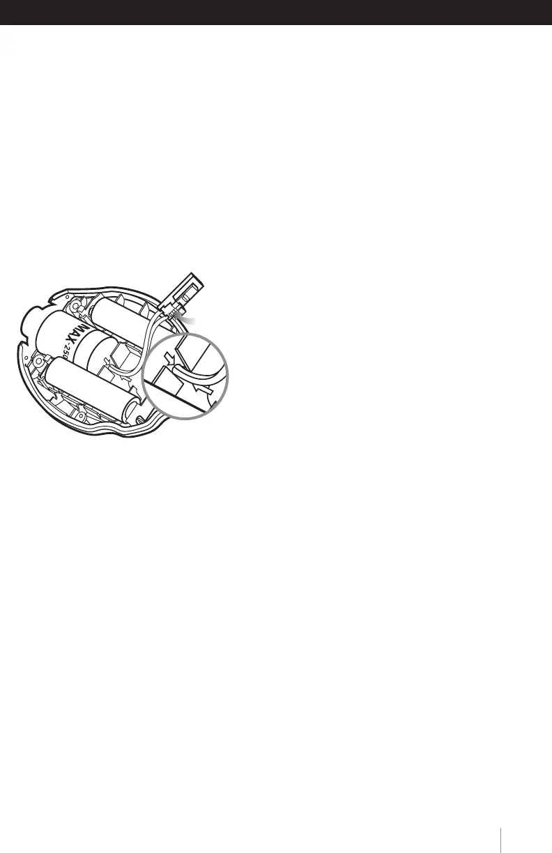
FIGURE 5
Lock Lever
HELPFUL HINT (MAXO2+ AE): Before closing the two case halves together, verify
that the keyed slot on top of the coiled cable assembly is engaged on the small tab
located on the back case. This is designed to position the assembly in the correct
orientation and prevent it from rotating. Improper positioning could hinder the case
halves from closing and prevent operation when tightening the screws.
7.0 CHANGING THE OXYGEN SENSOR
7.1 MAXO
2
®
+A Model
Should the oxygen sensor require changing, the
device will indicate this by presenting “Cal Err lo”
on the display after initiating a calibration.
To change the oxygen sensor, begin by
removing the three screws from the back of
the device. A #1 Phillips screwdriver is
required to remove these screws.
Once the screws are removed, gently separate
the two halves of the device.
Disconnect the oxygen sensor from the printed circuit board by pressing the un-
lock lever first and then pulling the connector out of the receptacle.
The oxygen sensor can now be replaced from the back half of the case.
HELPFUL HINT: Be sure to orient the new sensor by aligning the red arrow on the
sensor with the arrow in the back case. A small tab is located on the back case
that is designed to engage the sensor and prevent it from rotating within the case.
(figure 5)
NOTE: If the oxygen sensor is installed incorrectly, the case will not come back
together and the unit may be damaged when the screws are reinstalled.
Reconnect the oxygen sensor to the connector on the printed circuit board.
Carefully bring the two halves of the case together while positioning the wires to
ensure they are not pinched between the two case halves. Make sure the sensor
is fully inserted and in the proper orientation.
Reinsert the three screws and tighten until the screws are snug. Verify the unit
operates properly.
Thedevicewillautomaticallyperformacalibrationandbegindisplaying%ofoxygen.
11
W W W . M A X T E C I N C . C O M