2
M A N U F A C T U R E D B Y M A X T E C , I N C .
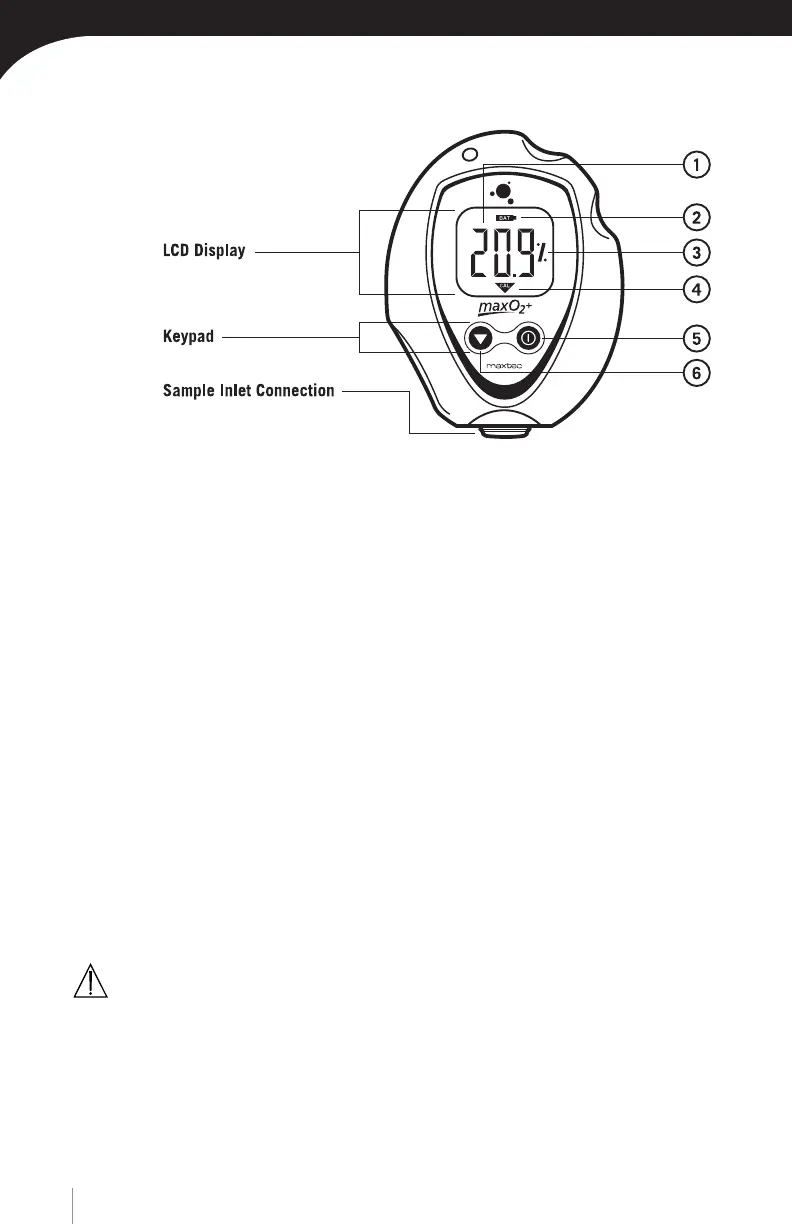
FIGURE 1
1.2 Component Identification
1.3 Component Description
1. 3 1/2-Digit Display-The31/2digitliquidcrystaldisplay(LCD)provides
directreadoutofoxygenconcentrationsintherangeof0-105.0%
(100.1%-105.0%usedforcalibrationdeterminationpurposes).The
digits also display error codes and calibration codes as necessary.
2. Low Battery Indicator - The low battery indicator is located at the top of the
display and is only activated when the voltage on the batteries is below a
normal operating level.
3. “%” symbol-The“%”signislocatedtotherightoftheconcentration
number and is present during normal operation.
4. Calibration symbol - The calibration symbol is located at the bottom of the
display and is timed to activate when a calibration is necessary.
5. ON/OFF Key - This key is used to turn the device on or off.
6. Calibration Key - This key is used to calibrate the device. Holding the key
for more than three seconds will force the device to enter a calibration mode.
CAUTION: The device will assume a percent oxygen concentration when cali-
brating. Be sure to apply 100% oxygen, or ambient air concentration to the
device during calibration or the device will not calibrate correctly.
Sample Inlet Connection
This is the port at which the device is connected to determine oxygen concentration.