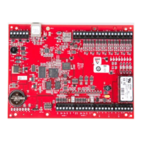
The eMAX-LP1502 is an IP Network-based Intelligent Area Controller designed for transaction processing, event reporting, and local database storage within the Maxxess eAXxess and eFusion Access Control Systems. It provides two card reader interfaces for controlling two physical barriers.
Function Description:
The controller communicates with a host system via its on-board 10-BaseT/100Base-TX Ethernet port or a Micro USB port (2.0) with an optional Micro USB to Ethernet adapter. Each reader port supports various reader protocols including TTL/Wiegand (D1/D0), TTL/Magnetic Stripe (Clock/Data), F/2F Protocol (standard or supervised), and 2-wire RS-485 OSDP. It also offers tri-state LED control and buzzer control (one-wire LED mode only). When configured for 2-wire RS-485 OSDP readers, each port can support two multi-dropped readers in an IN/OUT configuration, allowing for up to four readers in total.
The eMAX-LP1502 features four Form-C Contact relay outputs for door strike control or alarm signaling. These relays have dry contacts, rated at 5A @ 30Vdc resistive for Normally-Open (N/O) contacts and 3A @ 30Vdc resistive for Normally-Closed (N/C) contacts. Eight inputs are provided for monitoring door contacts, exit push buttons, and alarm contacts, configurable as unsupervised or supervised.
Important Technical Specifications:
- Primary Power: 12 to 24 Vdc ± 10%, 500 mA maximum (excluding reader and USB ports).
- Reader Ports Power: 600 mA maximum (adds 600 mA to primary power current).
- Micro USB Port Power: 5 Vdc, 500 mA maximum (adds 270 mA to primary power current).
- Memory and Clock Backup Battery: 3 Volt Lithium, type BR2330 or CR2330.
- microSD Card: Format: microSD or microSDHC; 2GB to 8GB.
- Host Communication: Ethernet: 10-BaseT/100Base-TX and Micro USB port (2.0) with optional adapter (pluggable model USB2-OTGE100).
- Serial I/O Device: One 2-wire RS-485 port, 2,400 to 115,200 bps, asynchronous, half-duplex, 1 start bit, 8 data bits, and 1 stop bit.
- Inputs: Eight unsupervised/supervised, standard EOL: 1k/1k ohm, 1%, ½ watt. Two unsupervised dedicated inputs for cabinet tamper and UPS fault monitoring.
- Outputs: Four Form-C relays with dry contacts. Normally open contact (NO) contact: 5 A @ 30 Vdc resistive. Normally closed contact (NC) contact: 3 A @ 30 Vdc resistive.
- Reader Interface Power (jumper selectable): 12 Vdc ± 10% regulated, 300 mA maximum each reader (input voltage (VIN) must be greater than 20 Vdc) OR 12 to 24 Vdc ± 10% (input voltage (VIN) passed through), 300 mA maximum each reader.
- Data Inputs: TTL compatible, F/2F or 2-wire RS-485.
- RS-485 Mode: 9,600 to 115,200 bps, asynchronous, half-duplex, 1 start bit, 8 data bits, and 1 stop bit. Maximum cable length: 2000 ft. (609.6 m).
- LED Output: TTL levels, high>3 V, low<0.5 V, 5 mA source/sink maximum.
- Buzzer Output: Open collector, 12 Vdc open circuit maximum, 40 mA sink maximum.
- Cable Requirements: Power and Relays: 1 twisted pair, 18 to 16 AWG. Ethernet: CAT-5, minimum. RS-485 (I/O Device Port): 1 twisted pair, shielded, 120 ohm impedance, 24 AWG, 4,000 ft. (1,219 m) max. Reader Port: 1 twisted pair, shielded, 120 ohm impedance, 24 AWG, 2,000 ft. (610 m) max. Alarm Input: 1 twisted pair, 30 ohms maximum.
- Environmental Temperature: -55 to +85 °C (storage), 0 to +70 °C (operating).
- Humidity: 5 to 95% RHNC.
- Dimension: 8 in. (203.2 mm) W x 6 in. (152.4 mm) L x 1 in. (25 mm) H.
- Weight: 9 oz. (255 g) nominal, board only.
- UL294, 6th edition Performance Levels: Standby Power: I, Endurance: I, Line Security: I, Destructive Attack: IV.
Usage Features:
- DIP Switches (S1): Configure operating modes such as normal operation, default user/password enable, factory default communication parameters, OEM default communication parameters, bulk erase prompt mode, and EP1502 emulation.
- Jumpers: Configure reader port power (12Vdc or VIN "Pass Through") and RS-485 End-of-Line (EOL) termination (ON/OFF). Jumper J7 for reader power select must be in the 12V position if input voltage (VIN) is greater than 20 VDC to prevent damage.
- Input Wiring: Input circuits can be configured as unsupervised (reporting open/closed states) or supervised (reporting open, closed, shorted, grounded, and foreign voltage states). Supervised circuits require two 1k ohm, 1% resistors located close to the sensor. Custom EOL resistances can be configured via host software.
- Relay Circuit Wiring: Form-C contacts allow for Normally Open (N/O) or Normally Closed (N/C) configurations for door strike control or alarm signaling. A diode is recommended to protect the relay from feedback generated by door lock mechanisms.
- IT Security: User accounts for the web configuration page should be created with secure passwords. DIP Switch 1 enables a default login (admin/password) for five minutes after being moved from OFF to ON. It is crucial to define at least one user account and set DIP switches to OFF before commissioning. The device should not be configured with an IP address accessible from the public Internet. Options are available to disable SNMP, Zeroconf discovery, and the web configuration module, and to enable data encryption over the host communication port.
- Web Configuration: The eMAX-LP controllers include an internal web page for configuring communication parameters. Default IP is 192.168.6.12, with default user 'admin' and password 'password'. The web interface allows setting IP address, subnet mask, default gateway, and DNS settings.
Maintenance Features:
- Memory Backup Battery: The static RAM and real-time clock are backed up by a lithium battery (BR2330 or CR2330) when input power is removed. This battery should be replaced annually. If data corruption occurs after power-up, all data (including flash memory) is considered invalid and erased, requiring re-downloading of configuration data.
- Bulk Erase Configuration Memory: This function can be used to erase all configuration and cardholder database (sanitizing the board), update OEM default parameters, or recover from database corruption causing continuous reboots. The process involves specific DIP switch settings and takes up to 60 seconds.
- Status LEDs: Provide visual feedback on power status, initialization progress, host communication activity, internal and external SIO communication, Ethernet traffic, speed, link status, input status (inactive, active, fault), and relay status (energized). LED 1 indicates Off-Line/On-Line and battery status (double flash for low battery). LEDs 1 & 4 flashing for 3 seconds indicate completion of memory erase.