13
ENG
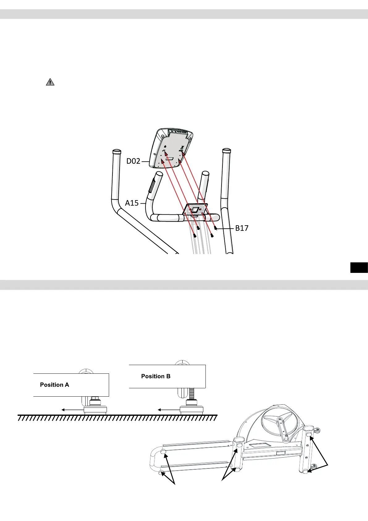
Step 16: Assembly of the Cockpit
Loosen and remove the four round head screws (B17) from the back of the cockpit (D02). Connect the cables
protruding from the cockpit (D02) with the cables protruding from the xed handlebar (A15).
Please note that the two cables of the hand pulse measurement have identical connections. The order of
connection does not matter. The other cables can be clearly identied by their connections. Secure the cockpit
(D02) to the cockpit holder on the handlebar (A15) with four screws (B17).
CAUTION:
Please make sure that the cables do not get crushed or damaged.
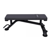
Make sure your exercise equipment is always level. In order to compensate for minor bumps or slopes in the
oor, adjustable feet are tted on the right and left of the front and rear stands and on the sliding frame. To make
sure the position of the device is level, rst turn all feet to the lowest position (position A). If necessary, adjust
the feet until the device is level and stable.
If the adjustment range of the levelling feet is not enough to allow the training device to stand safely, please
check the surface of the location and, if necessary, choose a dierent location, where a safe and level position
can be ensured.
Assembly
Levelling the Device
Adjustable foot Adjustable foot
Adjustable foot
Adjustable foot