6
To stop the Self-Cleaning cycle at any time, press CANCEL or
OFF/CANCEL. If the temperature is too high, the oven door will
remain locked and “cool” and “locked” or “
” will be displayed.
When “
” shows in the display, the door of the oven cannot be
opened. To avoid damage to the door, do not force the door open
when “
” is displayed.
Before self-cleaning, make sure the door is completely closed or
the door will not lock and the Self-Cleaning cycle will not begin.
Once the cleaning temperature has been reached, the electronic
control requires a 12 hour delay before another Self-Cleaning
cycle can be started.
The oven light will not function during the Self-Cleaning cycle.
Electronic Oven Control with Adjustable Clean Time (on
some models)
The Self-Cleaning cycle is time adjustable between 2 hours
30 minutes and 4 hours 30 minutes in 30 minutes increments.
Suggested clean times are 2 hours 30 minutes for light soil and
4 hours 30 minutes for heavy soil. The last 30 minutes of the cycle
is for cooldown.
IMPORTANT: When cooktop is in use, the Self-Cleaning cycle will
be disabled. When the Self-Cleaning cycle is in use, the cooktop
will be locked.
To Self-Clean:
1. Press CLEAN or SELF CLEAN.
2. Press the Temp/Time “+” or “–”, or “up” or “down” keypad to
enter the desired Self-Cleaning cycle time.
3. Press START.
The oven door will automatically lock. The Door Locked and
Clean indicator lights will be displayed. The time remaining will
also be displayed.
4. When the Self-Cleaning cycle is complete and the oven cools,
the Door Locked and Clean indicator lights will turn off.
5. When the oven is completely cooled, remove ash with a damp
cloth.
To exit the Self-Cleaning cycle before completed, press
CANCEL or OFF/CANCEL. The door will unlock once the
oven cools.
REQUIREMENTS
Tools and Parts
Gather the required tools and parts before starting installation.
Read and follow the instructions provided with any tools listed
here.
Tools needed
� Tape measure
� Flat-blade screwdriver
� Phillips screwdriver
� Level
� Hammer
� Hand or electric drill
� Wrench or pliers
� Marker or pencil
� Flashlight
� Torque Wrench
� Masking tape
� 1/4" (6.4 mm) drive ratchet
� 1/4" (6.4 mm) nut driver
� 3/8" (9.5 mm) and 5/16"
(8 mm) nut driver
� 1/8" (3.2 mm) drill bit (for
wood floors)
� Tin snips or large wire
cutters (for cutting
ground-link strap if
necessary)
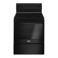
Parts supplied
Check that all parts are included.
� 3 - 10-32 hex nuts (attached to terminal block)
� 3 - Terminal lugs
A. Anti-tip bracket
B. #12 x 1
5
⁄
8
" (41 mm) screws (2)
� Anti-tip bracket must be securely mounted to floor or wall.
Thickness of flooring may require longer screws to anchor
bracket to floor.
Parts needed
If using a power supply cord kit:
� A UL listed power supply cord kit marked for use with ranges.
The cord should be rated at 250 V minimum, 40 A or 50 A that
is marked for use with nominal 1
3
⁄
8
" (3.5 cm) diameter
connection opening and must end in ring terminals or
open-end spade terminals with upturned ends.
� A UL listed strain relief.
Check local codes. Check existing electrical supply. See the
appropriate “Electrical Requirements” section.
It is recommended that all electrical connections be made by a
licensed, qualified electrical installer.
NOTE: Be sure to purchase only Whirlpool factory-certified parts
and accessories for your appliance. Your installation may require
additional parts. To order, refer to the contact information
referenced in your Quick Start Guide.
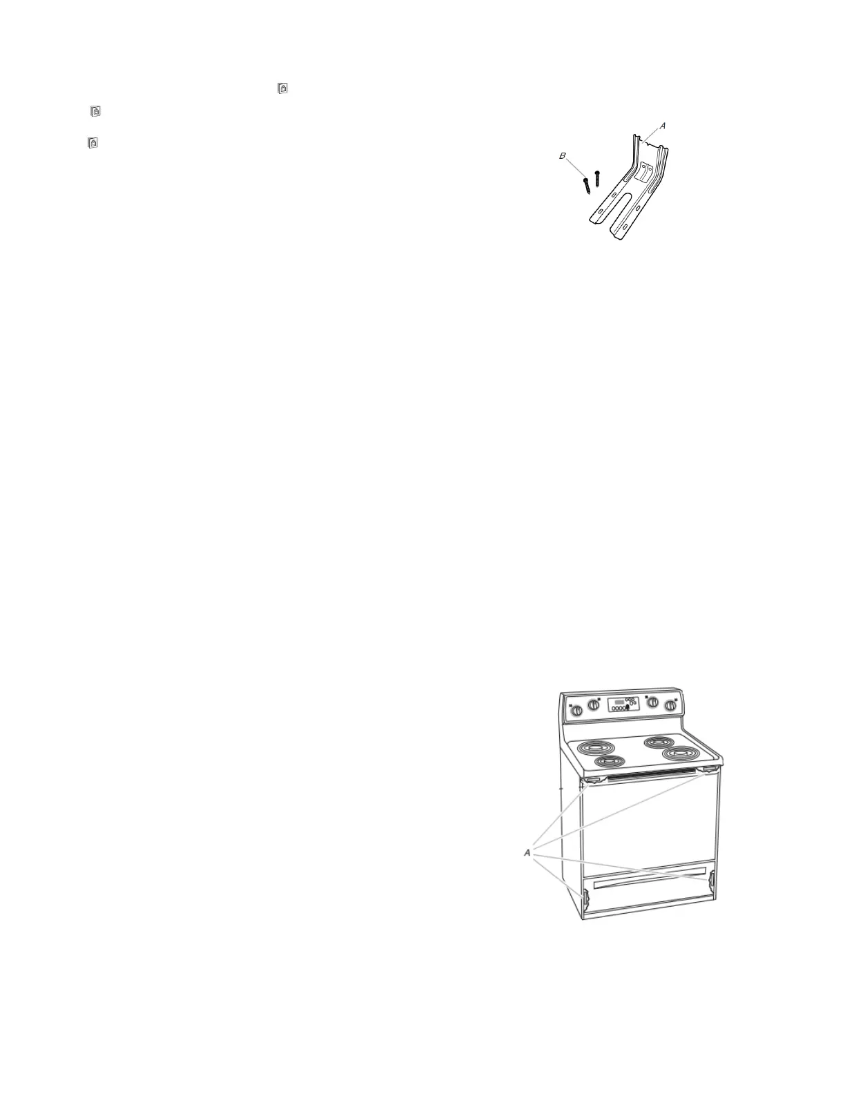
Location Requirements
IMPORTANT: Observe all governing codes and ordinances.
� It is the installer’s responsibility to comply with installation
clearances specified on the model/serial/rating plate. The
model/serial/rating plate is located on the frame behind a top
corner of the door or either side of the drawer.
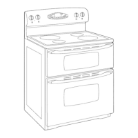
A. The model/serial/rating plate is located on the frame behind a top
corner of the door or either side of the drawer.