18
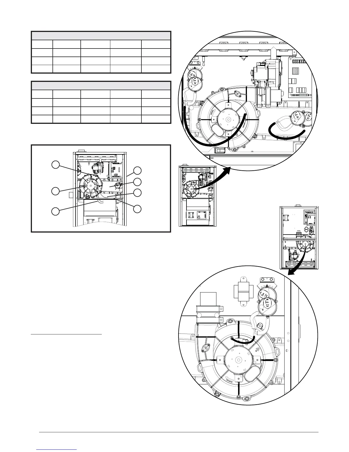
Figure 14. Inducer Assembly Rotation
2
5
1
4
6
3
7
7. Remove the cabinet plug (7) from side of furnace and
reinstall in hole on opposite side of cabinet.
8. If applicable, install condensate drain on the in-line
drain assembly. See Figures 38 - 40 (pages 47 - 49).
9. Reconnect the electrical harness (1) to the inducer
assembly (2).
10. Reconnect the inducer assembly ground wire (3) to
the blower deck (4) or door.
11. Verify proper operation as detailed on the furnace
label.
Pressure Switch Tubing
Figure 15 displays the proper routing of pressure switch
tubing for *TC furnaces. All upfl ow / horizontal furnaces
have two pairs of switches. One set is connected to the
static tap on the inducer assembly and the other to the
collector box. Downfl ow (*TL) furnaces require only one
pair of switches to be connected to the inducer’s static
tap. See Figure 16.
Table 4. Vent and Inducer Blower Options
Conventional (1 Pipe)
Vent Upfl ow Horiz. Right Horiz. Left Downfl ow
Right Option 1 N/A N/A Option 9
Up N/A Option 5 Option 6 Option 10
Left Option 2 N/A N/A Option 11
Direct Vent (2-pipe)
Vent Upfl ow Horiz. Right Horiz. Left Downfl ow
Right Option 3 N/A N/A Option 12
Up N/A Option 7 Option 8 Option 13
Left Option 4 N/A N/A Option 14
AIR FLOW
12 3
4
56 7
8
AIR
FLOW
12 3
4
56 7
8
Figure 16. Pressure Switch Tubing
for Downfl ow Furnaces
Figure 15. Pressure Switch Tubing for
*TC Upfl ow / Horizontal Furnaces