27
1. Setting the Autostage jumper in the SHORT position
signals the control to utilize an 8 minute delay between
LOW fi re and HIGH fi re when a call for heat is supplied
via 24V signal to W1. This setting is the same as
jumping R to W2
2. Setting the Autostage jumper in the LONG position
signals the control to utilize an 12 minute delay
between LOW fi re and HIGH fi re when a call for heat
is supplied via 24V signal to W1. This setting is the
same as jumping W1 to W2
Autostaging for Two-Stage Thermostats
The Autostage setting on the furnace control board (Figure
32, page 40) is disabled when shipped from the factory.
This feature will be not used when paired with a two-stage
thermostat. The autostage jumper setting (P7) must be
kept on NONE to allow the thermostat to adjust stages.
Please note that on certain thermostats, even without the
autostage jumper in the LONG position, W1 & W2 may
be energized at exactly the same time when a recovery
from a set-back begins, the user adjusts the set point,
or the system is powered on. If W1 & W2 are energized
at exactly the same time for any reason, the control will
operate in the autostage LONG (12 minute) mode. If the
autostage jumper is in the NONE position and autostaging
is activated unexpectedly for any of the reasons listed, it
will return to normal, staged operation after the completion
of the heating cycle.
Heat Anticipator
Set the heat anticipator according to the instructions
supplied by the thermostat manufacturer. To determine
the heat anticipator setting:
1. Add the current draw of the system components; or
2. Measure the current fl ow on the thermostat R & W
circuit after the circulating blower motor has started.
Dehumidifi cation Options
Both motor control boards (Figures 30 & 31, page 40)
have a DHUM connection that allows the system to
increase the amount of humidity that is removed from
the circulating air. This is accomplished by reducing the
CFM and allowing the cooling coil to become colder. This
will only occur when there is a call for cooling. There are
many ways that this can be electrically wired:
1. If the room thermostat incorporates a humidity sensor
and DHUM output, connect the DHUM on the
thermostat to the DHUM terminal on the motor control
board (Figure 27).
2. If using a separate humidistat, connect the
DHUM & R terminals on the humidistat to the
DHUM & R terminals on the motor control board.
In this option, the DHUM output of the humidistat must
be set to be normally open and closed when there is
a call for humidifi cation.
3. If a humidistat is not available, it is an acceptable option
to connect the R & DHUM terminals on the motor
control board together with a fi eld supplied wire. This
option causes the blower to run at a reduced CFM for
10 minutes after a call for cooling.
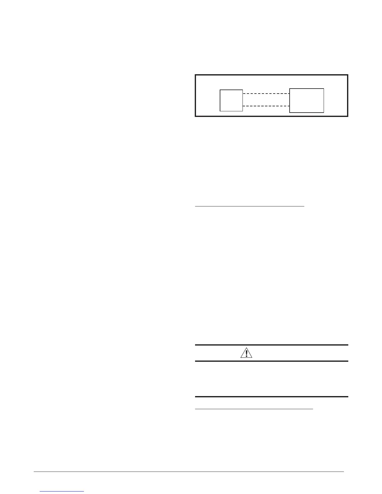
DHUM
R
R
DHUM
HUMIDISTAT
MOTOR
CONTROL BOARD
Figure 27. DHUM Wiring Confi guration
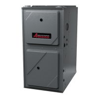
Blower Speed Confi guration
Two-stage furnaces use high effi ciency circulating air
motors that come in two variations and both are controlled
differently. The fi xed speed motor control board (Figure
30, page 40) controls the torque and the variable speed
motor control board (Figure 31) controls the airfl ow at a
constant CFM. Both boards use the same furnace control
board (Figure 32).
Fixed Speed Blower Applications
NOTE: This section applies only to furnaces with model
numbers suffi xed with two numbers, followed by a letter,
such as 35C or 45D. If your model has suffi x VA, VB,
VC, or VD, please consult the Variable Speed Blower
Application section.
The fi xed speed motor control board (Figure 30) contains
a set of dip switches for setting the blower speed. Use pins
1 to 4 to set the blower speed for heating and pins 5 to 8
to set the speed for cooling. To determine the appropriate
switch settings for your installation, see Table 9 (page 35)
for heating or Table 10 (page 36) for cooling.
For thermostats with a dehumidifi er output, use a fi eld
supplied wire to connect the thermostat’s dehumidifi er
output to the terminal marked DHUM. The thermostat
should be set so that the DHUM output should be high
(positive) when dehumidifi cation is needed. See also
Dehumidifi cation Options section.
CAUTION:
The terminal marked “Y1_IN” on the variable
speed motor control board is not an output to
drive the outdoor unit. DO NOT connect Y1_IN
on the motor control board to the outdoor unit.
Variable Speed Blower Applications
NOTE: This section applies only to models ending with
the suffi xes VA, VB, VC, or VD.
The variable speed motor control board (Figure 31, page
40) has a set of dip switches for setting the base blower
speed. Use pins 1 to 4 to set the blower speed for heating
and pins 5 to 8 to set the speed for cooling. To determine