23
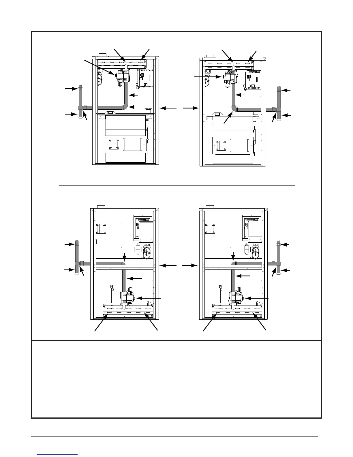
COMPONENTS:
(1) Automatic Gas Valve
(w/ manual shut-off)
(2) Burner Assembly (3) Dripleg
(4) Elbow (5) Ground Joint Union (6) Manifold
(7) Pipe Nipple (8 inch) (8) Plug (9) Shut - Off Valve
NOTE A: Some utilities require Shut- Off Valve to be 4 to 5 feet above fl oor.
NOTE B: Inducer assembly omitted for clarity of pipe installation.
Figure 22. Typical Gas Connections
6
4
2
UPFLOW MODELS
DOWNFLOW MODELS
1
See
Note “B”
See
Note “B”
Right Side Entry
Left Side Entry
Right Side Entry
Left Side Entry
See
Note “B”
See
Note “B”
1
7
4
3
9
9
3
See
Note “A”
See
Note “A”
5
5
7
1
2
6
6
7
1
See
Note “A”
See
Note “A”
8
2
4
3
9
5
8
9
3
5
6
2
7
8
4