FOR SERVICE TECHNICIAN ONLY - D O NOT REMOVE OR DESTROY POURLETECHNICIEN SEULEMENT - NE PAS ENLEVERNIDÉTRUIRE
NECÈIP8EGAPW10156735A.ONTRAP
o
W10156735A
➔
Si la résistance du bobinage du moteur est correcte,
il doit y avoir un circuit ouvert entre le moteur et le module
de commande électronique de la machine. Déterminer si
➔
Si la résistance de la bobine de démarrage est bien
supérieure à 3 , remplacer le moteur.
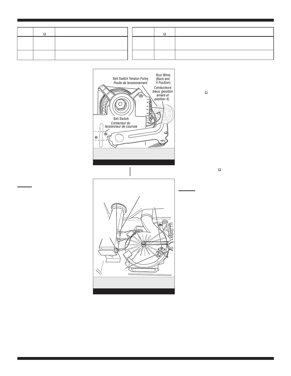
9. Contrôler le contacteur du tensionneur de courroie : mesurer
la résistance entre les deux conducteurs bleus (voir la figure 7)
tout en poussant vers le haut la poulie de tensionnement.
➔
Si la résistance mesurée passe de l’infini à quelques ohms
lors de la fermeture du contacteur, le contacteur du tensionneur
de courroie est en bon état. Sinon, remplacer le contacteur
➔
Si le contacteur de la courroie est en bon état et s’il
y a toujours un circuit ouvert, contrôler et réparer le câblage.
10. On peut identifier un problème du contacteur de la porte
lors du test de diagnostic du contacteur de la porte (page 2);
cependant, si cela n’a pas été fait, on peut exécuter les opérations
suivantes sans mettre la sécheuse sous tension. Brancher un
➔
Lorsque la porte est correctement fermée, on doit mesurer
une résistance de 0 à 2 (circuit fermé).
➔
Sinon, remplacer le contacteur de la porte. Voir figure 2,
page 5. Voir également à la page 13, Dépose du panneau
➔
If the resistance at the motor is correct,
there is an open circuit between the motor and
➔
If the Start winding resistance is much
greater than 3 Ω, replace the motor.
9. Check the belt switch by measuring resistance
between the two blue wires, as shown in figure 7,
➔
If the resistance reading goes from infinity
to a few ohms as pulley arm closes the switch,
➔
If belt switch is OK and there is still an open
circuit, check and repairthe wiring harness.
10. Door Switch problems can be uncovered in the
Door Switch Diagnostic Test on page 2; however, if
this was not done, the following can be done without
applying power to the dryer. Connect an ohmmeter
➔
With the door properly closed, the ohmmeter
should indicate a closed circuit (0–2 Ω).
➔
If not, replace the door switch assembly.
See figure 2, page 5; and Removing the Front
Thermal Fuse
Exhaust Thermistor
Coupe-circuit thermique
Heater
Element
Thermal Cut-Off
Inlet Thermistor/
High Limit Thermostat
Élément
chauffant
Thermistance d’entree/
thermostat de température
maximum
Thermistance - décharge
Fusible thermique
Thermal Components,
viewed from front.
Composants du système de
chauffage - vue avant.
Figure 8
TEST #4 Heater
This test is performed when either of the
following situations occur:
✔
Dryer does not heat
✔
Heat will not shut off
✔
Display flashes L2
This test checks the components making up the
heating circuit.
Dryer does not heat or display flashes L2:
Locate the components using figure 2, page 5,
and figure 8.
TEST N
o
4 Élément chauffant
On exécute ce test lorsque l’une des situations suivantes se
manifeste :
✔
Absence de chauffage
✔
Impossibilité d’arrêt du chauffage
✔
L’afficheur présente L2 avec clignotement
Avec ce test, on contrôle les composants du circuit de chauffage.
Absence de chauffage ou l’afficheur présente L2
avec clignotement :
À l’aide de la figure 2, page 5, et de la figure 8, identifier
les composants.
1. Unplug dryer or disconnect power.
2. Remove the front panel and drum
assembly to access the thermal components.
See Removing the Front Panel/Drum Assembly,
page 13.
3. Using an ohmmeter and referring
to the appropriate wiring diagram
(see pages 15 and 16), measure the
resistance across the high limit
thermostat.
➔
If an open circuit is not detected,
go to step 5.
➔
If an open circuit is detected,
go to step 4.
1. Débrancher la sécheuse ou déconnecter la source
de courant électrique.
2. Enlever le panneau avant et le tambour pour acceder
aux composants du système de chauffage. Voir Dépose
du panneau avant/tambour, page 13.
3. Utiliser un ohmmètre et consulter le schéma
de câblage approprié aux pages 15 et 16; mesurer
la résistance à travers le thermostat de température
maximum.
➔
Si aucun circuit ouvert n’est détecté, passer
à l’étape 5.
➔
Si un circuit ouvert est détecté, passer à
l’étape 4.
Winding Resistance
Contact Points of Measurement
MAIN
1.4–2.6
Blue wire in back at pin 4 and bare copper wire
terminal removed from pin 5 of black
drive motor switch
START
1.4–2.8
Blue wire in back at pin 4 and bare copper wire
terminal on pin 3 of black drive motor switch
Bobinage Résistance
Points de mesure
PRINCIPAL
1,4–2,6
Conducteur bleu à l’arrière sur broche 4, et conducteur de cuivre
nu déconnecté de la broche 5 du contacteur noir du moteur
d’entraînement
DÉMARRAGE
1,4–2,8
Conducteur bleu à l’arrière sur broche 4, et conducteur de cuivre
nu sur broche 3 du contacteur noir du moteur d’entraînement
Checking the
belt switch.
Contrôler le contacteur du
tensionneur de courroie.
Figure 7
machine control electronics. Check for failed
belt switch.
while pushing up the belt switch tension pulley.
belt switch is OK. If not, replace the belt switch.
across P8-3 (neutral, white wire) and P8-4 (door,
tan wire).
Panel/Drum Assembly, page 13.
le contacteur du tensionneur de courroie est défaillant.
de la courroie.
ohmmètre entre les points P8-3 (neutre, conducteur blanc)
et P8-4 (porte, conducteur tan).
avant/tambour.
 Loading...