Maytech Waterproof Remote Control User Manual_20191012 by Eric and Eileen
3
/
17
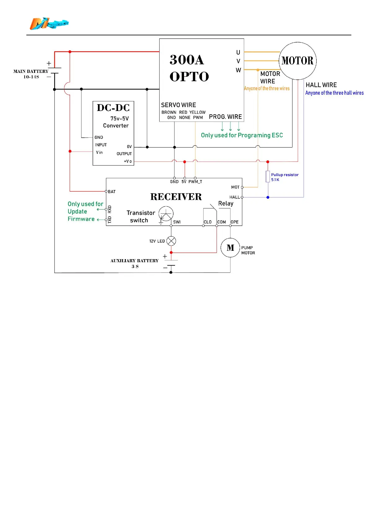
5.2 Receiver and Maytech ESCs based on Benjamin VESC wiring diagram:
5.2.1 If connect Motor hall sensor to Maytech VESC based controllers or VESCs, VESC internal pull-up
resistor will be used, so this application does not need an external pull-up resistor.
5.2.2 Cross connection of Receiver TXD/RXD and VESC RX/TX:
Receiver’s TXD>> VESC RX;
Receiver RXD>> VESC TX.
5.2.3 VESC supports UARR and PWM(PPM) throttle control. When use with Maytech waterproof remote,
you can select UART/PPM/PPM and UART three control options, and select corresponding control
in remote (“6. Speed source” and “11. VESC Thr”). We recommend to use PPM and UART control:
PPM to control throttle and UART to read voltage/current/ temperature/speed/etc. Please refer to
Item “16.2” and “16.5”in this manual.
5.2.4 Please set “Baudrate” to “115200 bps” in VESC_TOOL.