Do you have a question about the MayTech MTSKR1905WF and is the answer not in the manual?
First full waterproof remote, works well in water, especially for electric surfboards.
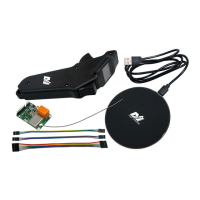
First wireless charging remote control in the industry for added convenience.
OLED display provides clear visibility of throttle and battery voltage.
Standard PWM signal output supports diverse applications like RC cars, boats, and robotics.
Supports motor RPM detection via motor phase wire or hall sensor wire.
Supports VESC communication protocol, allowing data display via the UART port.
Features one 30V 3A relay mechanical switch and one 20V 2A transistor electronic switch.
Details IP rating, trigger modes, sensor type, CPU, display, battery, and charging interface.
Specifies power supply, throttle signal output, voltage detection, RPM detection, and switch parameters.
The primary control for throttle input.
Button for menu navigation and function selection.
The control for braking input.
The screen showing operational data.
Interface for charging the remote.
Provision for attaching a wrist strap.
Identifies key connection terminals on the receiver, including power, motor, signal, VESC, and sensor wires.
Connection point for the 30V 3A relay switch.
Integrated antenna for wireless communication.
Wiring diagram for MTSF300A-OPTO ESC and receiver.
Notes on connecting hall sensor for RPM detection, including pull-up resistor requirements.
Discusses VESC internal pull-up resistor usage for hall sensor connections.
Explains the cross-connection between receiver TXD/RXD and VESC RX/TX for communication.
VESC supports UART and PWM throttle control, recommending PPM and UART usage.
Recommended VESC Baudrate setting in VESC_TOOL is 115200 bps.
ESC integrates voltage sampling, RPM measurement, and UBEC for simplified external wiring.
Describes the functions of the ESC's 10 signal wires for firmware, parameters, and RPM detection.
Includes one 7-pin and two 3-pin DuPont cables for connections.
Converts 18-75V DC to 5V, 1200mA for receiver power if ESC lacks supply.
Used for updating receiver firmware; requires separate purchase.
Remote supports QI standard wireless chargers for waterproof integrity. Charging time is under one hour.
Long press function button for 1s to switch on the remote.
Long press function button for 1.5s to switch off the remote.
Long press cycles through states like OFF, switch on/off the remote.
Short press from main interface to enter sub-menu or data setting.
Short press from pairing interface to quit pairing process.
Controls throttle signal output or brake signal based on position and mode.
Provides brake signal or enables cruise control in E-surf mode.
Selects speed signal source from Motor Wire, Hall Sensor, or VESC for RPM/Speed display.
Distance calculation is only supported in Esk8 mode for electric skateboards.
Distance is accumulated speed x time based on Motor Wire or Hall Sensor input.
Distance is calculated from VESC ABS data via UART port when VESC is selected as speed source.
Main battery voltage display functions in both Esk8 and Esurf modes.
Voltage obtained from VESC via UART or BAT port on receiver PCB.
Ensures correct main battery voltage display by maintaining common ground between receiver and battery.
Remote displays voltage in bars based on type/number, flashing when low.
Displays voltage, current, and temperature from VESC via UART port after proper connection.
Motor temperature measured via a built-in 10K NTC thermistor connected to the hall sensor connector.
VESC_TOOL requires setting the Beta Value for Motor Thermistor to 3950K.
Covers states, operation, current limits (3A), and usage recommendations for the relay switch.
Details transistor switch operation, voltage limits (5-12V), wiring cautions, and LED control.
VESC identifies remote throttle settings and offers two modes: Current and Duty Cycle.
Motor current is control target; free slide upon release, recommended for skateboards/surfboards.
Motor RPM is control target; instant stop upon release, suitable for differential control.
Details signal strength, battery voltage, control mode, throttle percentage, and switch status.
Shows motor RPM in ESurf mode, with display text varying based on speed source selection.
Explains navigation to speed/distance, unit settings, and speed source variations in Esk8 mode.
Esurf mode only displays motor RPM, not speed or distance.
Displays min/max voltage/current from VESC via UART, requiring VESC as speed source.
Displays VESC and motor temperature from VESC via UART, requiring VESC as speed source.
Enter main menu by holding the brake trigger to the end and pressing the function button.
Exit sub-menus to main menu, and main menu to interface, using brake trigger and function button.
Lists 11 main menu options including Thr. Mode, Batt. Type, Speed Source, and VESC Thr.
Instructions on how to select options using short and long presses of the function button.
Allows selection between ESK8 and Surfboard electric skateboard modes.
Select battery type (3.2V or 3.7V per cell) for accurate voltage display.
Set battery series number (1-18) to match battery for correct percentage display.
Initiates the pairing process between the remote and receiver.
Steps for pairing if not already paired, including success/failure indicators.
Calibrates throttle and brake triggers to ensure accurate PWM signal output.
Explains importance of speed source for RPM/Speed/Distance display; lists Hall Sensor, Motor Wire, VESC.
Set motor pole pairs (1-24) for accurate motor speed/RPM calculation from ERPM.
Set wheel diameter (40-200mm) in Esk8 mode for speed and distance calculation.
Set gear ratio (1.0-20.0) for speed/distance calculation based on motor/propeller RPM.
Select distance units between km and mile, affecting speed unit display (KM/H or MPH).
Configure VESC for UART communication and set baudrate for Current Mode or Duty Cycle control.
Explains VESC current mode, emphasizing setting max current for throttle linearity and motor performance.
Duty cycle mode uses motor speed as target; stops motor immediately on release, suitable for differential control.
Remote battery icon with 2 or less bars indicates the need for charging.
Connect wireless charger, place remote on it for automatic charging after 2 seconds.
The remote screen shows input voltage and current battery voltage during charging.
Charging stops automatically at 4.2V; charging without supervision is prohibited.
Charge the remote once a month if not in use to preserve battery life.
Placeholder for future firmware update instructions.
| Brand | MayTech |
|---|---|
| Model | MTSKR1905WF |
| Category | Remote Control |
| Language | English |