- 11 -
shaft until the recess in the worm gear hub is snug
against the retaining ring.
3. Press bearings (3) on each end of shaft. Make sure
bearings are butted against worm gear shoulders.
4. If bearing races are replaced make sure new races
are properly seated.
5. Set worm gear and shaft assembly into gearbox
housing. Assemble cover (9) and one.010” shim
#05401 (13) into place.
6. Apply down pressure to cover and check shaft for end
play, no end play & no pre-load.
7. Remove cover and install the proper shims (13) for no
end play.
8. Brush a light coat of oil on o-ring groove and inside lip
of cover. Roll o-ring (6) over the inside lip and into
groove in the cover.
9. Install seal (1) into cover from outside to inside edge
of retaining ring groove. Be sure it is installed square
and flat.
10. Install retaining ring (23) into cover.
11. Use a piece of thin plastic over shaft to protect seal
and install cover into gearbox housing. Secure with
two flange bolts (30) and two flat head screws (31).
12. Rotate shaft, there should be a little drag. If there is
too much drag another shim should be added until a
slight seal drag is felt. If there is side play in the shaft
a shim must be removed.
13. Measure main shaft run out. Maximum acceptable
total indicator run out is.0035 inches.
14. Apply pipe sealant to threads and Install drain plug
(32) and relief valve (22) if removed.
15. Brush a light coat of oil on o-ring (24) & roll over inside
lip and into groove of retaining cap (10).
16. Install two 010” shims #05360 (12) with retaining cap
on drain plug side of gearbox with four flange bolts
(29). Torque bolts to 90 in/lbs in an “X” pattern.
17. Press bearings (4) on each end of worm shaft (15).
Make sure bearings are butted against worm shaft
shoulders.
18. Install the worm shaft (15) with bearings (4) into
gearbox housing. Gears must be meshed properly.
19. Install bearing cap (20) and apply pressure towards
gearbox (8). Rotate worm shaft and check for end
play and gear backlash.
20. Remove bearing cap and install proper shims (12) for
no back lash & no end play.
21. Install new seal (21) into bearing cap (20) from
outside. Make sure the seal is installed square & flat.
22. Brush a light coat of oil on o-ring groove, roll o-ring
(24) over inside lip and into groove of bearing cap.
23. Pour one can (21 oz.) of #05700 oil into worm shaft
opening. Install cap and secure with four flange bolts
(29). Torque bolts to 90 in/lbs in an “X” pattern.
24. Apply a small amount of loctite #290 to inside of
spacer (16) and push onto the worm shaft (15)
through oil seal (21) and up against bearing (4) inside
of the gearbox housing.
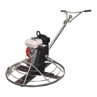
Handle Removal/Installation
Refer to Standard Handle Assembly, page 24.
1. Remove bottom lock nut (27) from pitch cable (6).
2. Slide pitch cable end out of pivot pin (7) and remove
jam nut (28) from pitch cable (6).
3. Disconnect shorting wires (9) from engine.
4. Disassemble throttle wire from engine.
5. Remove screws (26), washers (24) and lock nuts (27)
from handle tube (18) and slide handle off of gear box
tube. For F36 only
, remove top screw only (26),
washers (24) & lock nut (27) in gear box tube, loosen
only the lower screw (26).
6. Slide the handle assembly off the handle mounting
tube.
7. To re-assemble the handle, slide the handle
assembly on to the handle mounting tube, guiding
pitch cable end thru cable slide, F46 only.
8. Install screws (26), washers (24) and lock nuts (27).
For F36 only
, install top screw (26), washers (24) &
lock nut (27) in gear box tube, tighten lower screw
loosened in step #5.
9. Assemble hex jam nut (28) to pitch cable (6)
10. Slide the threaded end of the pitch cable (6) into the
pivot pin (7) and assemble lock nut (27) to cable (6).
11. Route safety switch wire between engine and belt
guard and reconnect to engine.
12. Install throttle wire to engine.
Gas Spring Replacement
Refer to EZ Pitch Handle Assembly, page 28.
GAS SPRING MAY BE UNDER PRESSURE.
1. Move the EZ pitch handle to the most extend,
pitched, position to take pressure of the gas spring,
see figure #2.
2. See the “Handle Removal” section of the manual to
remove the handle from the trowel.