- 12 -
3. Remove flange lock nut (34) securing gas spring (18)
to bracket (14).
4. Remove button head screw (30) and washer (6) from
tube (22) just below gear assembly (15).
5. Slide EZ pitch assembly out of top of tube (22).
6. Unhook EZ pitch lever (19) from pitch cable links (16).
7. Remove three spiral pins (29) from activating shaft
(11), handle (9) and EZ pitch lever (19).
8. Slide activating shaft (11) out of gear assembly (15)
and remove handle assembly (9).
9. Remove gas spring (18) from handle assembly (9)
and replace with new gas spring.
10. Slide activating shaft (11) thru handle (9), gear
assembly (15) and EZ pitch lever (19) and reinstall
spiral pins (29). Note position of EZ pitch lever (19).
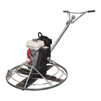
11. Lock handle assembly (9) in extended position as
shown in figure #2.
12. Slide pitch cable links (16) into gear assembly (15)
over top of activating shaft (11) and hook into EZ pitch
lever (19).
13. Slide EZ pitch assembly into top of handle tube (22),
guiding cable into top of cable slide (13) F36 handle
only, see figure #3.
14. Align hole in gear assembly (15) with hole in top of
handle tube (22) and install washer (6) and button
head screw (30) with blue loctite.
15. Assemble bottom end of gas spring (18) to mounting
bracket (14) with lock nut (34).
16. Reinstall handle assembly to trowel per the “Handle
Removal/installation” section of this manual.
Low Vibration handle Cable Replacement
Refer to Low Vibration Handle Assembly, page 26.
1. See the “Handle Removal” section of the manual to
remove the handle from the trowel.
2. Remove screws (11), washers (27) and remove
safety switch assembly (#24).
3. Turn pitch control knob all the way counterclockwise.
4. Remove button head screw (28) and washer (10)
from tube below pitch control knob (3).
5. Remove socket head screw (31) from slot on right
side of handle tube (21).
6. Slide pitch cable assembly out top of tube, guiding
threaded end thru cable slide on bottom end of tube.
7. Remove button head screw (30) from shaft adapter
(22) to remove cable (6).
8. Assemble new cable (6) to shaft adapter (22), with
screw (30), note cable position for F36 or F46 handle
9. Slide pitch cable assembly into top of handle tube
(21), guiding cable into top of cable slide (23), F36
handle, see figure #3.
10. Install socket head screw (31) to shaft adapter (22)
thru slot on right side of handle tube (21).
11. Align hole in bearing (4) with hole in top of handle
tube (21) and install button head screw (28) and
washer (10).
12. Slide handle assemble on handle mounting tube on
gear box & reinstall hardware removed in the “Handle
Removal” section of this manual.
Shorting Wire Replacement
Refer to Standard Handle Assembly, page 24.
1. Assemble shorting wire (#9) to both screws on safety
switch (15). Reset screw height as shown in figure
#7.
2. Remove short wire with ring terminal from end of
harness (9). Rout harness inside small tube on
handle (18) & between engine and belt guard as
shown in figure 8.
3. Connect bullet terminal to engine shut-off switch wire.
Reattach short wire & assemble ring terminal to lower
right engine shroud screw, as shown in figure #8.
High Speed Clutch Spring Replacement
Refer to Drive Assembly, page 20.
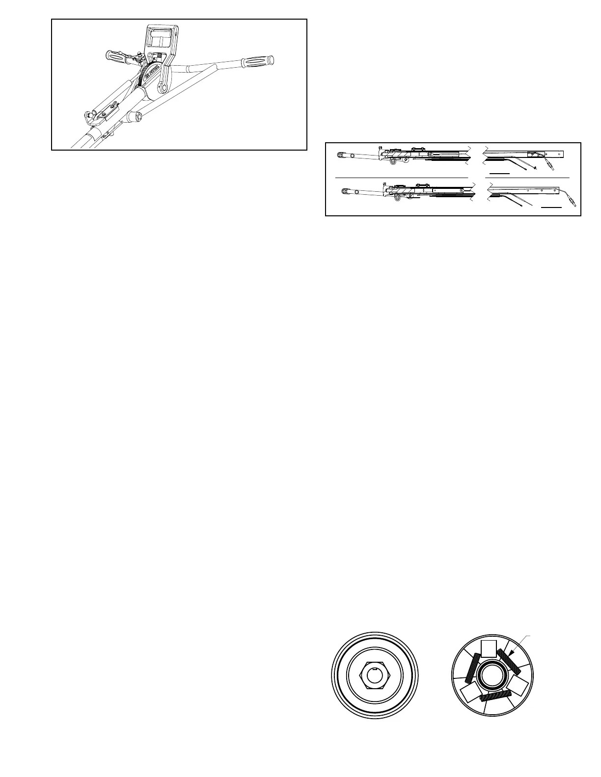
1. Remove clutch assembly from trowel.
2. Place service tool #20860 inside drive clutch and
secure in bench vise.
Figure 4