- 10 -
SERVICE
Assembly and disassembly should be performed by a
service technician who has been factory trained on MBW
equipment. The unit should be clean and free of debris.
Pressure washing before disassembly is recommended.
• Prior to assembly, wash all parts in a suitable cleaner or
solvent.
• Check moving parts for wear and failure. Refer to the
Replacement section in this manual for tolerance and
replacement cycles.
• All shafts and housings should be oiled prior to pressing
bearings. Also, ensure that the bearings are pressed
square and are seated properly.
• All bearings, seals, o-rings and gaskets should be
replaced when rebuilding gearbox.
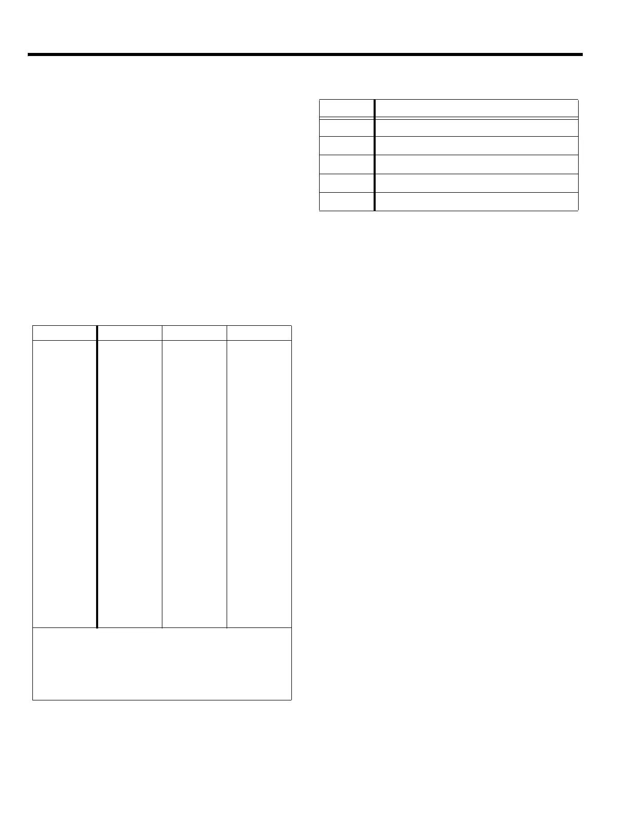
Torque Chart
Service Tools
Gearbox Disassembly
Refer to Gearbox Assembly, page 16.
1. Remove handle see handle remove section, belt
guard & drive assembly (page 20), guard ring (page
22).
2. Loosen square head set screw (page 16, #18) until
gearbox can be lifted off the spider assembly.
3. Flip gearbox (8) over and set it on guard ring pads.
4. Remove yoke arm (11) by removing one retaining
rings (7),securing pivot rod (14) and slide rod out of
hole.
5. Remove bolts (30) and flat head screws (31) that hold
cover (9) to the gearbox housing (8).
6. Remove cover and discard shims (13) and o-ring (6).
7. Remove retaining ring (23) and seal (1) from cover,
discard seal.
8. Pull out shaft (18) with bearings (3) and worm gear
(17) and drain oil out of gearbox.
9. Press bearing (#3) and worm gear (17) off long side
of shaft (18).
10. Remove key (19) and retaining ring (2) from shaft.
11. Press remaining bearing (#3) off of shaft.
12. Remove bolts (29) and bearing cap (20). Discard
shim gasket (12) and o-ring (24).
13. Remove worm shaft (15) and bearings (4).
14. Remove retaining cap (10), discard shim gasket (12)
and o-ring (24).
Gearbox Assembly
Refer to Gearbox Assembly, page 16.
1. Lightly oil shaft (18). Install key (19) and retaining ring
(2) onto shaft.
2. With retaining ring end of shaft down, press worm
gear (17) onto shaft. Make sure the longer hub of
worm gear is down. Worm gear should be pressed on
SIZE GRADE 2 GRADE 5 GRADE 8
1/4-20 49 in
•lbs 76 in•lbs 9 ft•lbs
1/4-28 56 in
•lbs 87 in•lbs 10 ft•lbs
5/16-18 8 ft
•lbs 13 ft•lbs 18 ft•lbs
5/16-24 9 ft
•lbs 14 ft•lbs 20 ft•lbs
3/8-16 15 ft
•lbs 23 ft•lbs 33 ft•lbs
3/8-24 17 ft
•lbs 26 ft•lbs 37 ft•lbs
7/16-14 24 ft
•lbs 37 ft•lbs 52 ft•lbs
7/16-20 27 ft
•lbs 41 ft•lbs 58 ft•lbs
1/2-13 37 ft
•lbs 57 ft•lbs 80 ft•lbs
1/2-20 41 ft
•lbs 64 ft•lbs 90 ft•lbs
9/16-12 53 ft
•lbs 82 ft•lbs 115 ft•lbs
5/8-11 73 ft
•lbs 112 ft•lbs 159 ft•lbs
5/8-18 83 ft
•lbs 112 ft•lbs 180 ft•lbs
3/4-16 144 ft
•lbs 200 ft•lbs 315 ft•lbs
1-8 188 ft
•lbs 483 ft•lbs 682 ft•lbs
1-14 210 ft
•lbs 541 ft•lbs 764 ft•lbs
1-1/2-6 652 ft
•lbs 1462 ft•lbs 2371 ft•lbs
M 6 3 ft
•lbs 4 ft•lbs 7 ft•lbs
M 8 6 ft
•lbs 10 ft•lbs 18 ft•lbs
M 10 10 ft
•lbs 20 ft•lbs 30 ft•lbs
CONVERSIONS
in
•lbs x 0.083 = ft•lbs
ft
•lbs x 12 = in•lbs
ft
•lbs x 0.1383 = kg•m
ft
•lbs x 1.3558 = N•m
Part No. Description
07276 Adjustment Tool, Tilt Arm Parallelism
07277 Adjustment Tool, Tilt Arm Height Gage
07279 Installation Tool, Spider Bushing (#06459)
16421 Bearing Spool Tool (Constant Force)
20860 Clutch Drive Tool