30107-10 Rev. 2.5 | 24NOV2020
Page 11
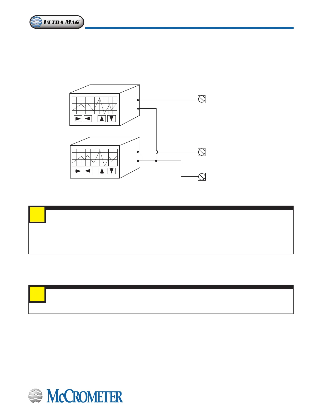
4-20mA Hook-Up
Isolated 4-20mA current loops are used to output ow data to external devices. Maximum load impedance is 1,000Ω, and
the maximum voltage without load is 27VDC. The converter has the capability to detect a loss of load on this output. To
disable this function set the value “mA Val. Fault” under the ALARMS menu to zero (see section 5.4). A graphical example of
the usage of the current loop with external device is shown below:
If the external device requires a voltage input, a precision resistor placed across the input terminals of the external device
will change the current to voltage. Calculate the required resistor using Ohm’s law (V = I x R). For example, a 250Ω resistor
will provide an input voltage of one to ve volts with the transmitter range being set from 4mA to 20mA. An additional 4
to 20mA loop output is available.
Figure 12. 4-20mA Hook-Up
IMPORTANT
The converter powers the 4-20mA loops. Do not use external power for the 4-20mA loop as it may cause
permanent damage to the converter.
4-20mA Devices
Terminal 24 FORWARD FLOW
OUT1 4-20mA
Terminal 25 REVERSE FLOW
OUT2 4-20mA
Terminal 23 COMMON
OUT 1 / OUT2 4-20mA
IMPORTANT - RESISTOR REMOVAL FOR 4-20mA OUTPUTS
It is required to remove the resistors from terminals 23 & 25 and/or 23 & 24 before attaching 4-20mA cables.
FORWARD FLOW: Remove the resistor from terminals 23 and 24.
REVERSE FLOW: Remove the resistor from terminals 23 and 25.
See Section 3.1, "Terminal Block Diagram", Figure 6.
i
i
30124-60 Rev. 1.3 | 17APR2020
Page 9
CONNECTING WIRES TO TERMINALS

 Loading...