30107-10 Rev. 2.5 | 24NOV2020
Page 12
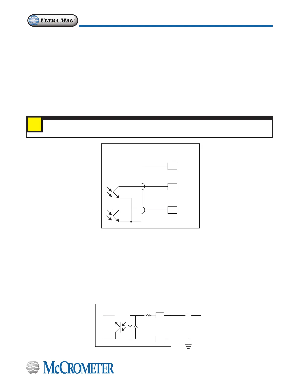
Opto-Isolated Pulse Output and Opto-Isolated Input Hook-Up
3.4 Opto-Isolated Pulse Output Hook-Up
The outputs are open collector transistor outputs used to communicate with or activate external devices.
• Opto-isolated output with collector and emitter terminals oating and freely connectable
• Maximum switching voltage: 40 VDC
• Maximum switching current: 100mA
• Maximum saturation voltage between collector and emitter 1.2V@100mA
• Maximum switching frequency (load on the collector or emitter, RL=470Ω, VOUT=24VDC): 1250Hz
• Maximum reverse current bearable on the input during an accidental polarity reversion (VEC): 100mA
• Isolation from other secondary circuits: 500 V
IMPORTANT
Digital outputs are not isolated from each other. All digital outputs MUST use the same power source.
i
Figure 13. Opto-Isolated Pulse Output Diagram
OUT 1
OUT 2
COMMON
EMITTER
18
17
19
3.5 Opto-Isolated Input
• Opto-isolated input
• 500 V isolation
• 2-40 VDC on voltage
• Input programming per input menu, will perform functions set to ON.
Input example:
Figure 14. Opto-Isolated Input Diagram
10K
24V
+
-
Push button
switch
15
16
30124-60 Rev. 1.3 | 17APR2020
Page 10
CONNECTING WIRES TO TERMINALS
Opto-Isolated Pulse Output Hook-Up
Opto-Isolated Input

 Loading...