30107-10 Rev. 2.5 | 24NOV2020
Page 7
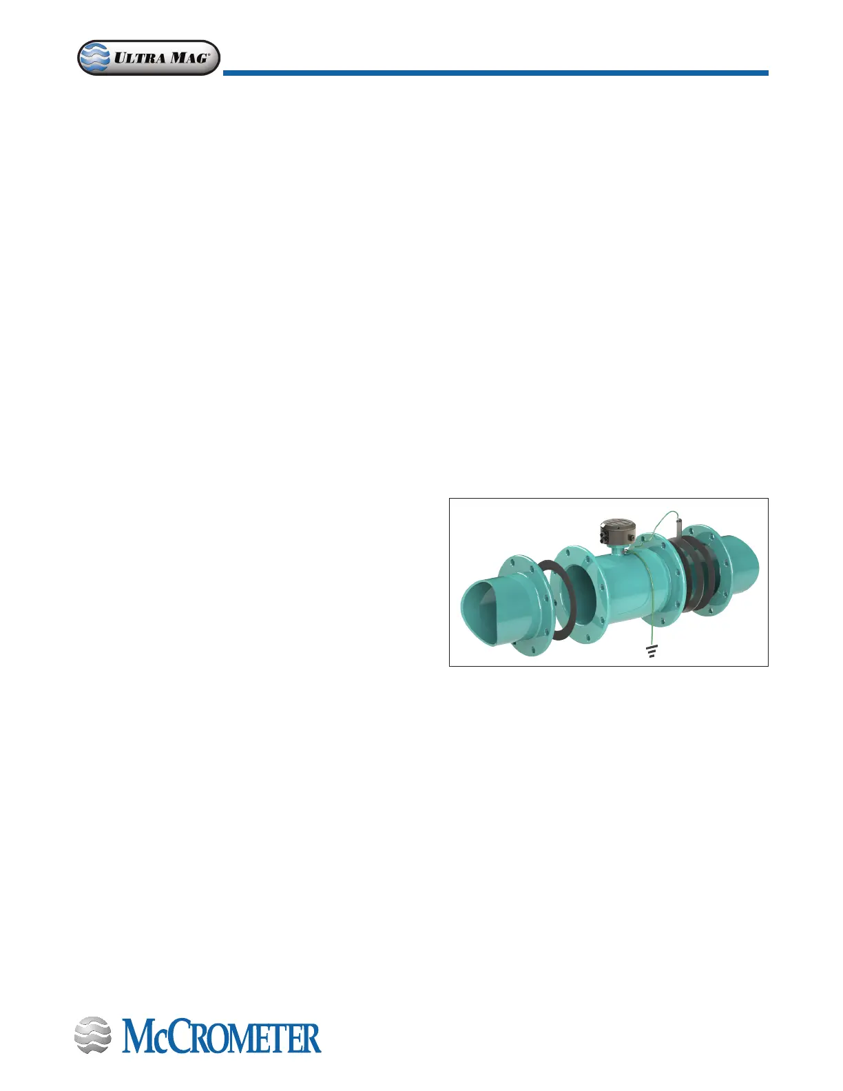
Sensor Grounding and Electrical Interference
Electrical Grounding
The sensor body must have electrical contact with the media. This is achieved via a grounding ring or grounding button.
NOTE: The grounding ring is optional only on 4” through 12” models. For best performance, grounding rings are
recommended for all sizes.
Always ensure that the converter and the sensor are grounded (earthed) correctly. The grounding of the sensor and
converter ensures that the equipment and liquid have an equal potential. For most installations the quality of grounding
by the provided cabling assures the sensor is properly grounded and additional grounding of the sensor is not required.
However, in instances where this is not the case, i.e. the equipment and uid do not have an equal potential, such as where
the installation location and/or media is subjected to electrical interference, additional grounding steps may be required.
Consult an electrician experienced with instrumentation installations to determine if electrical interference is present. For
further information on installation environments and sensor grounding, please contact McCrometer Technical Support.
Lines With Cathodic Protection
On meters installed on a line with cathodic protection it may be necessary to insulate the meter from the line. Consult your
cathodic protection vendor for instructions.
Speci cation Sheet
Ultra Mag Flow Meter with ProComm Converter
30107-09 Rev. 5.1 | 11MAY2020
Page 7
DIMENSIONS AND WEIGHTS
2" and 3" Models Body Style
C
B
A
Grounding Rings are 0.125" thick.
Grounding the meter body for safety according to national
(NEC) or local electrical codes is recommended on ALL meter
installations.
For best performance, grounding the uid column is
recommended when the meter is installed in an electrically
noisy environment, such as with VFD pumps or nearby electrical
systems with insu cient grounding.
Conductive or uncoated pipe - The uncoated pipe ange can
be used to establish a connection to earth ground.
Plastic or internally coated pipe - Grounding rings can be installed to establish a connection to earth ground
See the Ultra Mag IOM Manual, Lit. # 30119-03, for more information on grounding con gurations using grounding rods
and grounding rings.
METER GROUNDING RECOMMENDATIONS
D
C
B
A **Grounding Rings are 0.125" thick.
E
Meter
Type
Pipe Size
(Nominal)
Meter
Pipe ID
Flow Ranges
GPM
Standard
.2 to 32 FPS
Min - Max
DIMENSIONS
(Lay Lengths)
Est. Shipping
Weight (lbs.)**
A* B C D E
UM06 UM08 UM06 UM08 UM06 UM08
Use model shown below at left for dimensions
Wafer
style
2"
1.625 2 - 310 4.5 4.5 4.0 6.5 7.25 n/a n/a 9.6 10.1
3" 2.625 5 - 700 4.5 4.5 4.0 7.0 7.75 n/a n/a 11.3 11.8
Use model shown below at right for dimensions
Steel
ange
2” 2.117 2 - 340 11.00 11.00 6.70 6.00 6.50 7.90 9.26 93 107
3” 3.220 5 - 730 13.40 13.40 6.70 7.50 8.25 9.40 10.01 97 111
* Laying lengths for meters with ANSI Class 150 Flanges are equal to UM08 laying lengths
** For remote mount meters, add 4 lbs for ProComm converter.

 Loading...